SC-F2000 Revision C
DISASSEMBLY & ASSEMBLY Disassembly and Assembly Procedure 77
Confidential
3.4.3.6 REAR COVER SUB ASSY
1. Remove the two Locking Wire Saddle.
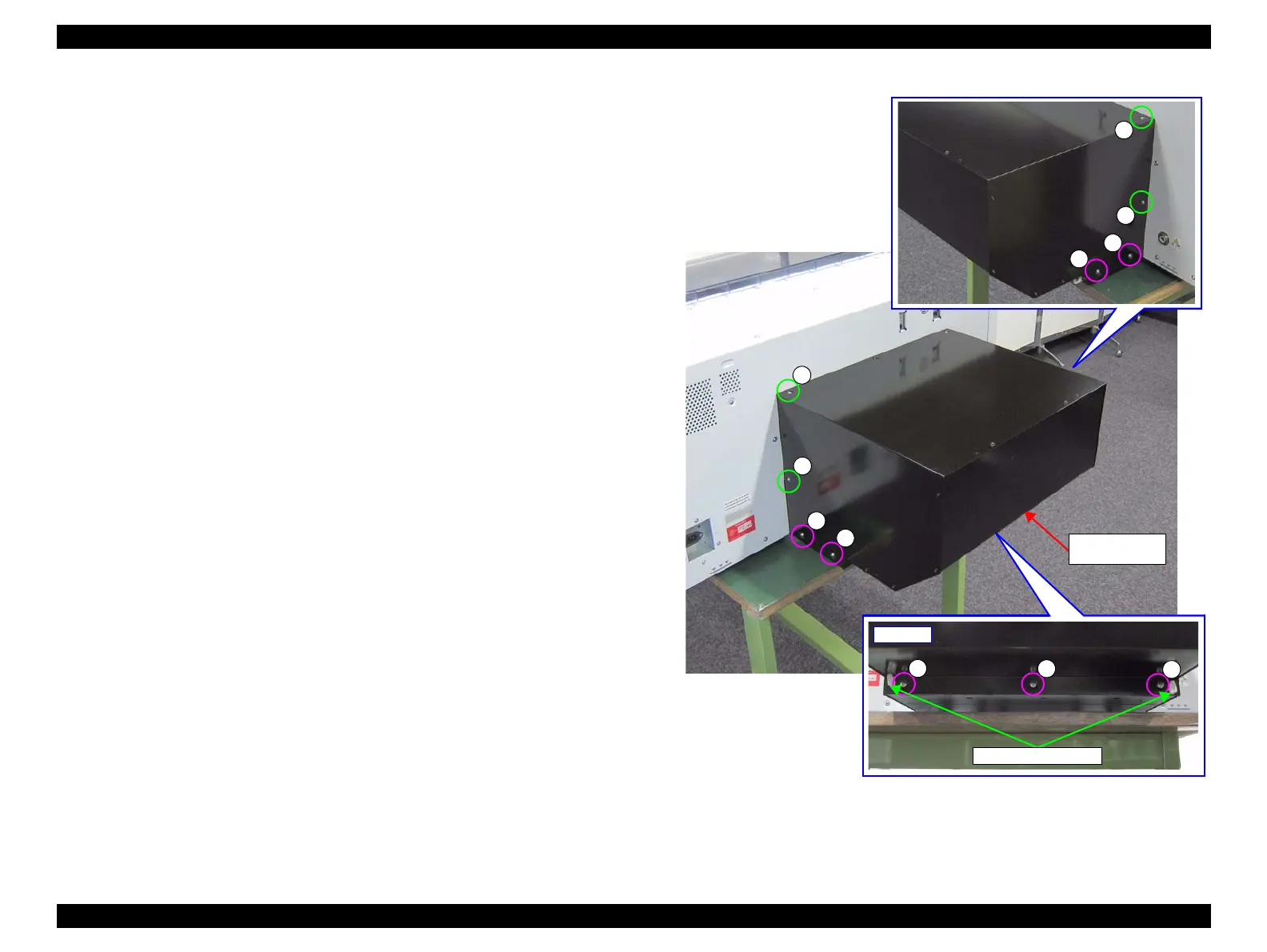
2. Remove the eleven screws that secure the REAR COVER SUB ASSY.
A) Silver M4x10 Sems S-tite screw: 7 pcs
B) Silver M3x8 Cup S-tite screw: 4 pcs
Figure 3-20. Removing the REAR COVER SUB ASSY (1)
A
A
A
Locking Wire Saddle
Rear side
 Loading...


