EPSON Stylus Photo R1900/R2880/R2000/R2000s/SC-P400 Series Revision I
Adjustment Adjustment Items and Overview 142
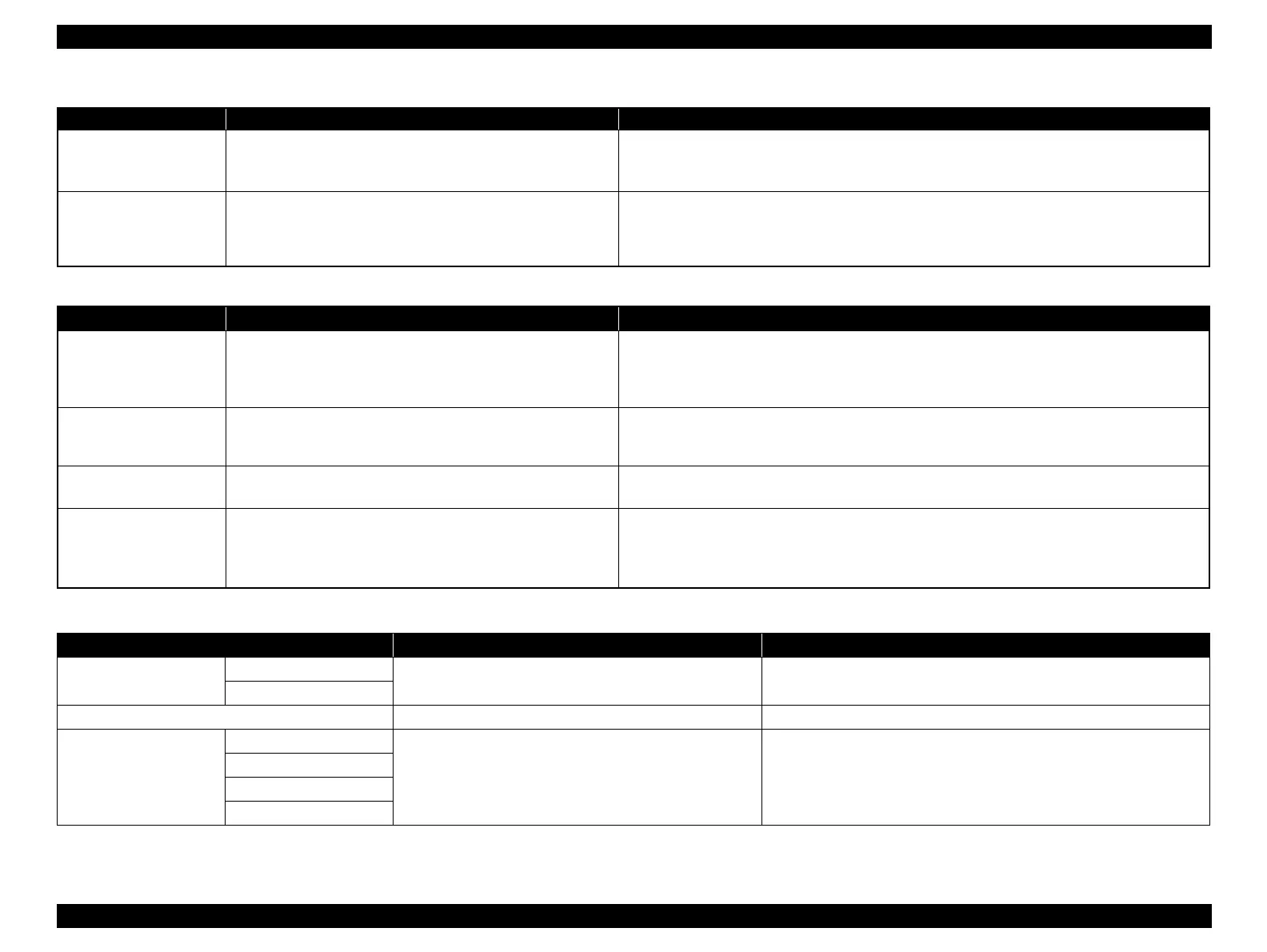
CR motor heat protection
control
This adjustment is made to measure the manufacturing
variations of the CR Motor and PS Board to make the most of
the motor capabilities for motor heat generation control.
1. Select/execute this function in the Adjustment Program.
2. After execution, the variations are automatically measured and the measurement values are
written to the EEPROM on the Main Board.
CR motor heat protection
control
(Maximum value)
CR Dispersion Measurement can be performed only when the
Carriage Shaft is new. To reduce the ancillary work in servicing,
enter the worst value (on which heat generation limit is easily
imposed) if the Carriage Shaft has not been replaced.
1. Select/execute this function in the Adjustment Program.
2. After execution, the dispersions are automatically measured and the worst value is written to the
EEPROM on the Main Board.
Table 5-2. Maintenance Functions
Function Item Purpose Method Outline
Ink charge This function is used for Print Head replacement to drain
Shipping Liquid of the after-sales service part in the head flow
path and simultaneously fill ink in the head flow path to make all
nozzles printable and stabilize the ink in the Print Head.
1. Select this function in the Adjustment Program.
2. Transfer the factory-set command (CL execution command (Initial Ink Charge) is used as the
command) to the printer to make the printer perform Initial Ink Charge operation.
Head cleaning This function is used to execute cleaning 3 (CL3) when ink is
not delivered from the Print Head properly, e.g. dot missing or
skewed injection.
1. Select this function in the Adjustment Program.
2. Execute CL3.
Waste ink pad counter This function is used to read and reset the Waste Ink Counters. 1. In the Adjustment Program, select data read or reset from this function.
Before executing this function, replace the Waste Ink Pads on both the 0 digit and 130 digit side.
High Voltage Module
inspection
This function is used to confirm the supply voltage from the
module falls within the specified range correctly.
1. Select this function in the Adjustment Program, set the High Voltage Module to On.
2. Using the tester, measure the voltage between the frame (near 130 digit side) and the screw
securing the electrode cable to confirm the measured voltage falls within the range of 240V to
500V. (For the location of the screw securing the electrode cable, see Figure 4-62. (p98).)
Table 5-3. Additional Functions
Function Item Purpose Method Outline
Final check pattern print A4 size Use this to check if the all adjustments have been properly
made.
The all adjustment patterns are printed automatically.
US Letter size
EEPROM dump Use this to read out the EEPROM data for analysis. The all EEPROM data is automatically read out and stored as a file.
Printer information
check
Manual CL counter Use this to read out information on the printer operations. The printer information is automatically read out.
I/C exchange CL counter
Timer CL counter
Print path counter
Table 5-1. Adjustment Items
Adjustment Purpose Method Outline

 Loading...


