EPSON WF-C5790/WF-C5790a/WF-C5710/ET-8700/WF-C5210/WF-C5290/WF-C5290a Revision A
Configuration and operating principles Operating principles 61
Confidential
3.3.5.2 Operating principles
OVERVIEW
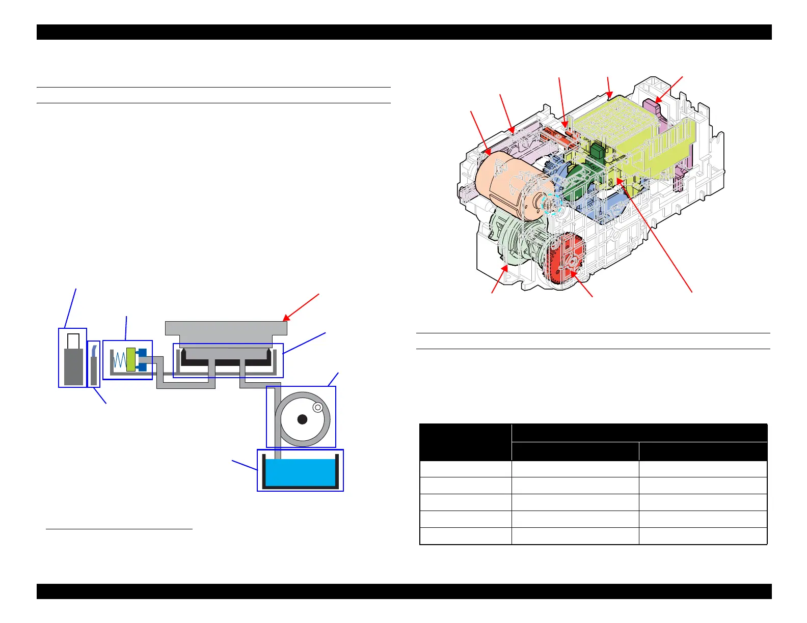
The inksystem mechanism of this product employs the direct acting type
1
and
consists of the carriage lock mechanism, wiper mechanism, capping
mechanism, pump mechanism, and venting valve (valve mechanism).
All the mechanisms are driven by the pump motor. The drive force of the pump
motor is transmitted to each mechanism via transmission parts, such as the
pump-drive compound gear, clutch gear, intermittent gear, cam, and drive
lever.
Additionally, this product utilize a maintenance box (waste ink pad) that retains
waste ink from the cap, with which users can replace ink themselves.
Figure 3-40. Inksystem Mechanism (Simplified Model)
Figure 3-41. Inksystem Mechanism
DRIVE PATH
The ink system mechanism is driven by the Pump Motor. The relationship
between the Pump Motor rotational direction and operation of each part is as
follows.
1. There are two types of the capping: direct acting type and sliding type. In the direct acting type, the cap moves up and
down independently of the carriage and caps the printhead. In the sliding type, the printhead is capped (the cap is
moved up) when the carriage pushes the cap slider.
Cap mechanism
Waste ink tray
(waste ink pad)
Pump mechanism
Valve mechanism
Wiper mechanism
Carriage lock mechanism
Printhead
Table 3-22. Pump motor rotational direction and operation of the inksystem
Mechanism
Rotational direction of the Pump Motor
a
a. Rotational direction seen from output shaft
CW CCW
Wiper Wiping position Passing
Cap Drop Rise (capping)
Pump Release Suction
CR Lock Drop (CR Lock release) Rise (CR Lock set)
Venting Valve Open Close
Cap
Wiper
Carriage lock lever
Pump unit
Venting valve
Pump-drive compound gear
Pump motor
Pump encoder sensor