Operation & Software Manual
270
Direct Drives & Systems
Chapter E: Appendixes ETEL Doc. - Operation & Software Manual # DSC2P 903 / Ver. F / 3/6/05
0
Clears sequence in ram memory and
sets default K value in ram memory
1 Clears sequence in ram memory
2 Sets default K value in ram memory
POP.<AXIS>
Clears all levels of the call stack.
Every time a CAL command is
executed, or the sequence goes to
label 80 (error process label), the
sequence line is stacked. It is possible
to stack 256 times before overflow
PWR.<AXIS>=<P1>
Power on if <P1> = 1 or power off if
<P1> = 0. The first power on does an
phasing according to K90. A power off
followed by a power on resets the
errors
REI.<AXIS>
Performs a RIE followed by a RET in
one time (cannot be interrupted)
RES.<AXIS>=<P1>
Restores the saved user variable (X
register), parameters (K register),
sequences (S register), look-up table
(L register), trigger (E register),
real-time interrupt (R register), float (F
register) and axis number in ram
memory according to <P1>
0
Restores sequence S, user look-up
table L, user variable X, parameters K,
trigger E, real-time interrupt R, float F
and axis number from flash to ram
memory if all the switches of the DIP
switch are set to 1
1
Restores sequence S and user look-
up table L from flash to ram memory
2
Restores user variable X, parameters
K, trigger E, real-time interrupt R, float
F and axis number from flash to ram
memory if all the switches of the DIP
switch are set to 1
RET.<AXIS>
Returns from subroutine, the
accumulator (XAC) is restored
RID.<AXIS>
Disables real-time functions. K190.# =
0 has the same effect
RIE.<AXIS>
Enables real-time functions. K190.# =
1 has the same effect
RSD.<AXIS>=<P1>
Puts the controller in hard reset if
<P1> = 255
RST.<AXIS>
Resets the error flags of the controller
(bit#10 of SD1). If this command is
executed in the error label routine
(:80), the pending error bit is cleared
(bit#0 of SD2)
SAV.<AXIS>=<P1>
Saves the current user variable (X
register), parameters (K register),
sequences (S register), look-up table
(L register), trigger (E register),
real-time interrupt (R register), float (F
register) and axis number in flash
memory in function of <P1>
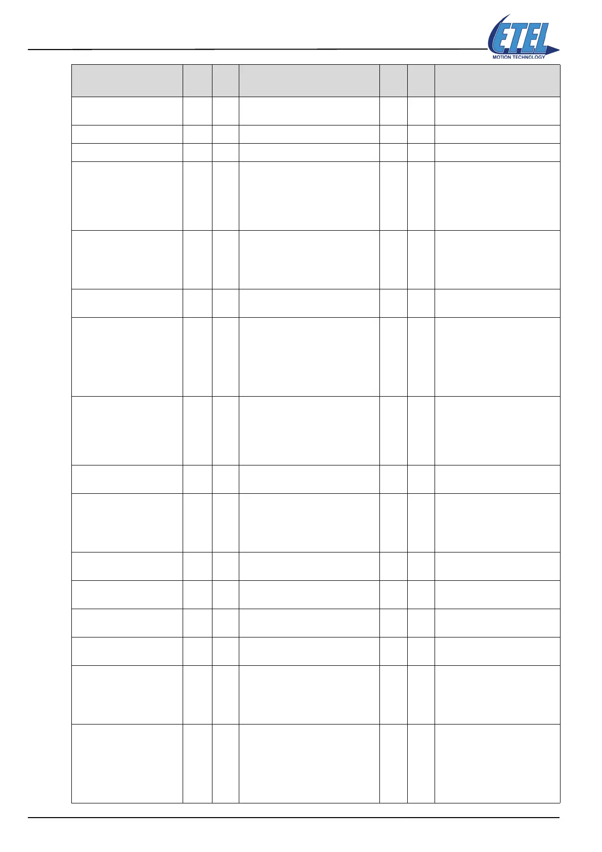
Syntax
Val
<P1>
Bit #
<1>
Comment for commands
and parameter <P1>
Val
<P2>
Bit #
<P2>
Comment for parameter <P2>
 Loading...
