119
SYSTEM ANALYSIS
IGNITION OUTPUT TESTS
6
Ignition Voltage Test
Use the Evinrude Diagnostics software Monitor
screen to check ignition voltage to the primary
ignition circuits of the ignition coils.
Results:
• KEY ON (not running) - 125 V ± 10, Ignition
voltage is GOOD, check voltage with outboard
running.
• KEY ON (not running) - less than 125 V ± 10,
check system voltage to EMM. Refer to System
Voltage Test on p. 118. Note: Key ON voltage
will not be constant (fluctuates 125 - 200 V
range)
• “RUNNING” - 200 V ± 10, Ignition voltage is
GOOD.
• “RUNNING” - less than 200 V ± 10, check stator
output to EMM. Refer to System Voltage Test
on p. 118 and STATOR TESTS on p. 136
Low or no voltage on EMM ignition circuit:
• Check system voltage (55 V) input to ignition
circuit on pin 4 of EMM J1-B connector.
Static Ignition Test
Perform the static ignition test using Evinrude
Diagnostics software and an inductive timing light.
IMPORTANT: DO NOT use a spark checker tool
with E-TEC models. Radio Frequency Interfer-
ence (RFI) generated by the arcing current can
cause erratic behavior in the EMM.
The outboard must NOT be running and the emer-
gency stop switch lanyard must be installed.
Connect timing light pickup to the secondary cir-
cuit (spark plug lead) of the cylinder being tested.
Activate test and observe timing light strobe for
consistent flash.
IMPORTANT: You may need to remove shield-
ing from wire if pickup does not read signal.
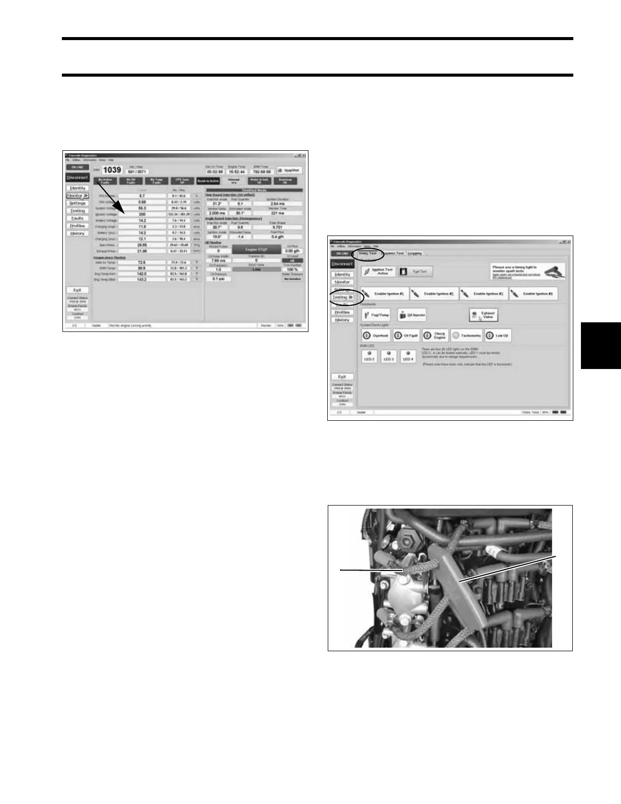
Engine Monitor Screen, Ignition Voltage 006751
Static Tests Screen 006752
1. Timing light pick-up
2. Spark plug lead
005319
1
2