231
POWERHEAD
POWERHEAD DISASSEMBLY
11
Crankcase Disassembly
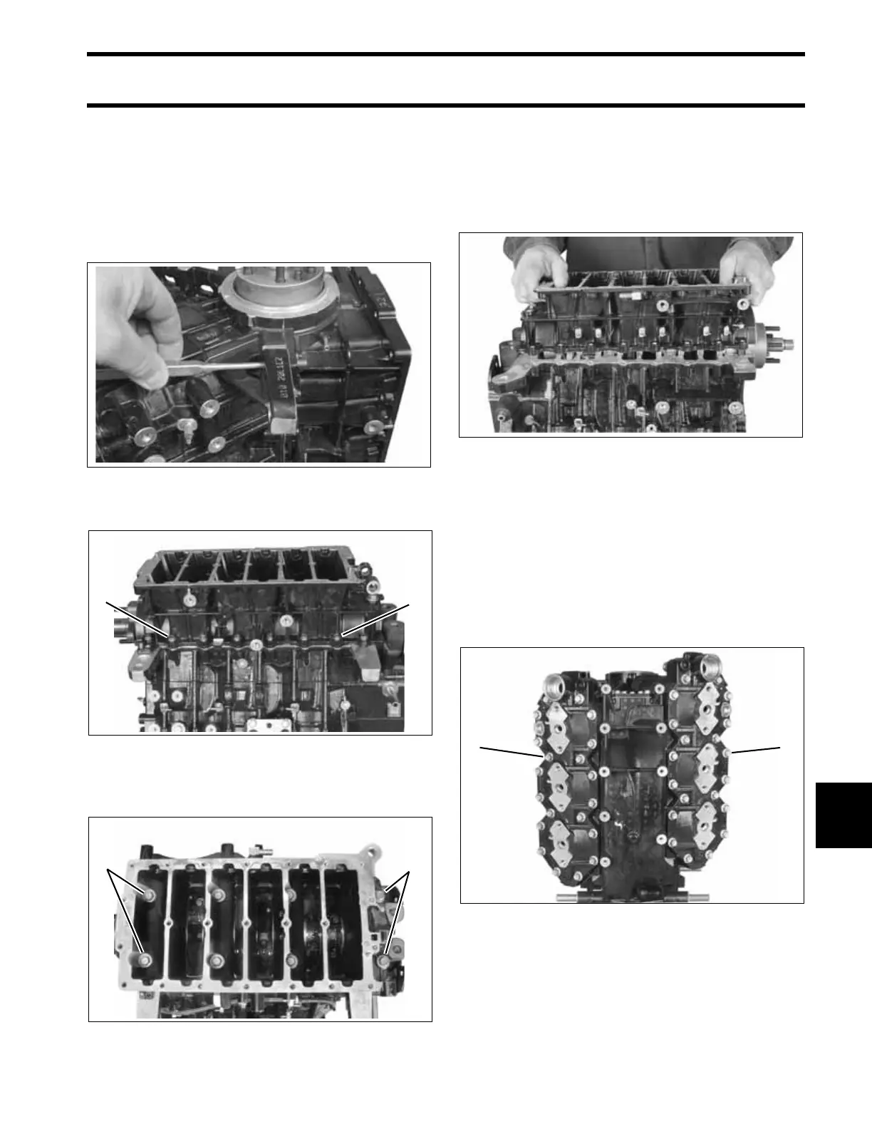
Use a 1/8 in. diameter pin punch to push crank-
case taper pin toward the front side of the engine.
IMPORTANT: Do not use a tapered punch or
any other tool that could jam in or damage the
taper bore when removing the pin.
Remove crankcase flange screws.
Loosen in stages and remove the main bearing
screws.
Separate crankcase and cylinder block. It may be
necessary to tap on crankshaft with a rawhide or
rubber mallet to loosen.
Carefully remove the crankcase from the cylinder
block to avoid damaging the crankshaft seal rings.
Cylinder Head Removal
Remove thermostat cover and thermostat assem-
bly. Refer to THERMOSTAT SERVICING on
p. 223.
Loosen in stages and remove cylinder head
retaining screws. Remove the cylinder head.
Discard thermostat seal and O-rings.
005305
1. Flange screws (12 on V4; 16 on V6) 005306
1. Main bearing screws (6 on V4; 8 on V6) 005313
11
11
005304
1. Cylinder head screws (28 on V4; 40 on V6) 005302
11