95
ENGINE MANAGEMENT MODULE (EMM)
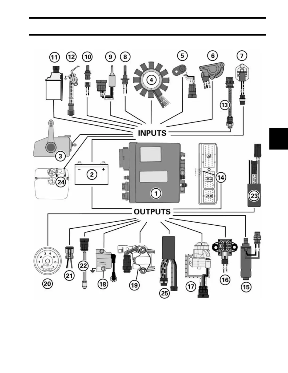
EMM INPUTS AND OUTPUTS DIAGRAM
5
EMM INPUTS AND OUTPUTS DIAGRAM
1. Engine Management Module (EMM)
2. Battery (12 volt)
3. Key switch (switched B+, start signal)
4. Stator
5. Crankshaft Position Sensor (CPS)
6. Throttle Position Sensor (TPS)
7. Neutral Switch
8. Air Temperature Sensor (AT)
9. Oil Pressure Sensor (component of 17)
10. Engine Temperature Sensor(s)
11. Water in Fuel Sensor / Fuel Filter
12. Trim / Tilt Sending Unit
13. Water Pressure Sensor
w/adaptor harness
14. LED indicators
15. Fuel Pump (high pressure)
16. Starter Solenoid
17. Oil Injection Pump and Manifold
18. Ignition Coil
19. Fuel Injector
20. Tachometer/SystemCheck Gauge
21. Diagnostic Connector
22. CANbus adaptor harness (NMEA 2000®
23. Trim and Tilt Relay Module
24. Oil Level Switch
25. Exhaust Valve Relay Module (V4)