53
INSTALLATION AND PREDELIVERY
OUTBOARD RIGGING
2
board side of the powerhead. Secure all cables
with tie-straps.
IMPORTANT: After installation, make sure
there is enough clearance for all cables to avoid
binding or chafing through all engine steering and
tilting angles.
Control Cable Installation
Refer to Control Cable Identification on p. 44.
Remove remote control cable trunnion covers and
cable attachment hardware.
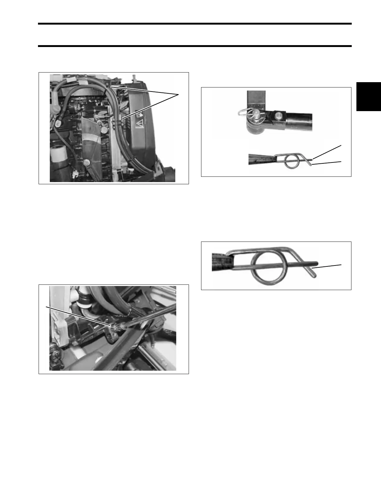
Cable Retainer Clip Installation
When installing retainer clips on control arm link-
age pins, clips should be locked and must not be
bent or deformed.
For proper installation, review the following steps:
• Place washer on pin.
• Position retainer clip with straight section on the
bottom and angled section on the top.
• Use long nose pliers to insert straight section of
clip into linkage pin hole.
• Push the clip towards the hole while lifting on
the curved end with the pliers.
• Be sure retainer clip fully engages the pin.
• Lock the retainer by moving the angled section
behind the straight section.
Shift Cable Installation and Adjustment
Place the shift cable on the shift lever pin and
install the washer and retainer clip.
IMPORTANT: Do not bend or deform clip.
Confirm that the remote control, gearcase, shift
linkage, and shift cable are in NEUTRAL.
Hold the shift linkage in NEUTRAL.
Push and pull on the shift cable and observe the
cable slack. Position the casing guide in the cen-
ter of the slack.
Adjust shift cable trunnion to align with center of
the trunnion block. Place cable trunnion in trun-
nion block.
1. Anchor points 004949
1. Trunnion covers 004955
1
1
1. Straight section
2. Angled section
DP0818
DP0817
Locked Retainer Clip
1. Angled section behind straight section
DP0817A
1
2
1