146
ELECTRICAL AND IGNITION
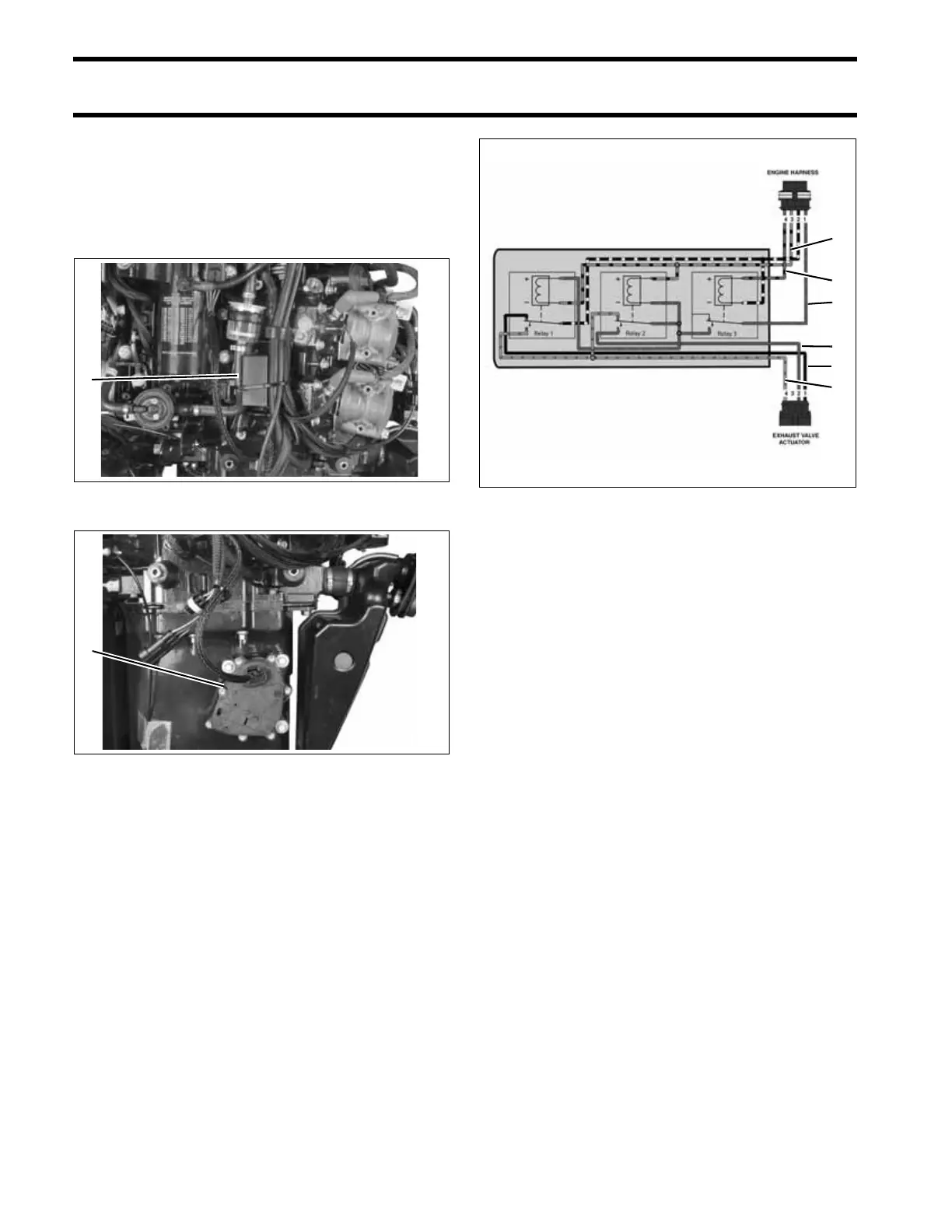
EXHAUST VALVE RELAY TESTS
EXHAUST VALVE RELAY
TESTS
The exhaust valve relay module controls the
exhaust valve actuator.
Operation
When the outboard is running, the fuel pump cir-
cuit (purple/black wire) provides 12V to activate
relay 3. Relay 3 provides fused 12V (red/purple
wire) to relay 1 and relay 2.
The EMM controls the exhaust valve by grounding
the blue/black wire.
When the blue/black wire is NOT grounded, fused
12V is supplied to the exhaust valve actuator
through the orange/red wire and the actuator is
grounded through the black wire on relay 1.
When the blue/black wire IS grounded, relay 1
and relay 2 are activated. Relay 2 supplies fused
12V to the exhaust valve actuator through the red
wire and the actuator is grounded through the
orange/red wire.
1. Exhaust valve relay module 005374
1. Exhaust valve actuator 005247
1
1
Exhaust Valve Relay Module Diagram
1. Purple/Black wire
2. Red/Purple wire
3. Blue/Black wire
4. Black wire
5. Orange/Red wire
6. Red wire
005429
3
1
2
6
4
5