220
COOLING SYSTEM
OPERATION
OPERATION
All models use a two-stage cooling system
design. The cooling system is dependent on water
pump pressure and controlled by thermostat and
pressure valve operation.
IMPORTANT: Restricted or inadequate water
flow through the outboard reduces cooling system
performance and may lead to severe powerhead
damage.
Cylinder Block / Cylinder Head
Cooling
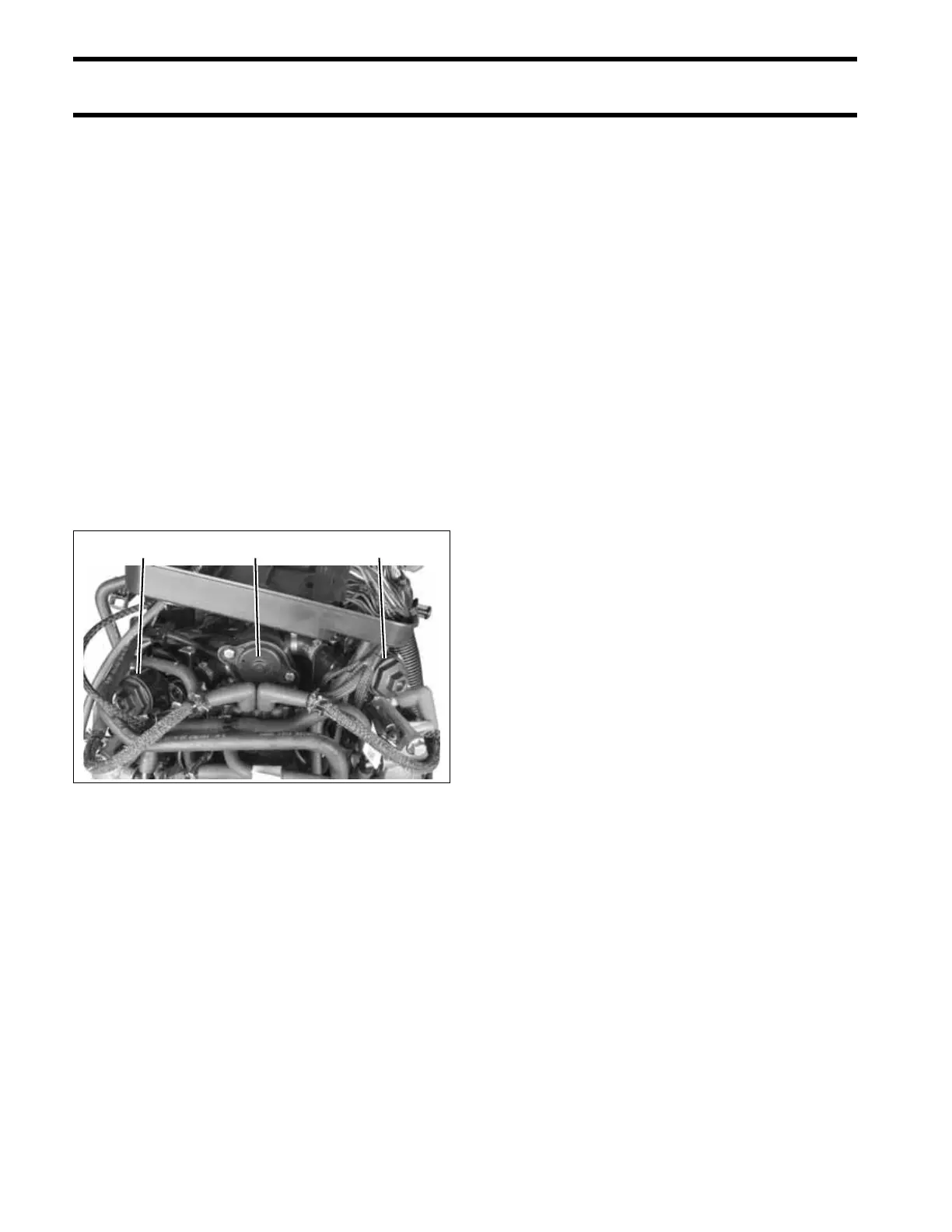
The flow of water through the cylinder block and
cylinder heads is controlled by two thermostats
and one external pressure valve. The pressure
valve is connected by hoses to the top of the block
and each cylinder head.
The thermostats and pressure valve control the
flow of water entering the vertical water passages
of the cylinder heads.
At low speed, the pressure valve is against the
seat and the thermostats are closed. Warm water
from the cylinder block gradually migrates to the
thermostat pocket at the top of each cylinder
head.
The thermostat opens when the water tempera-
ture reaches approximately 143°F (62°C).
When the thermostat opens, water flows down
through the cylinder head to a passage in the cyl-
inder block. Water flows through the block to the
exhaust housing and then out of the outboard.
At higher speeds, water pressure opens the
pressure relief valve at approximately 2500 RPM.
Water flows through the valve and bypasses the
thermostats. Hoses route the water flow from the
pressure valve to the vertical water passages
below the thermostats. All water flows through the
cylinder heads to the outlet passages of the block
and then exits through the adapter housing.
This pressure controlled water outlet circuit pro-
vides a “high flow” discharge of water during high
speed operation.
This cooling system configuration provides “bal-
anced cooling” at higher RPM by using one pres-
sure valve to control the discharge of water
through both cylinder heads.
EMM and Vapor Separator
Cooling
Cooling water is routed from the top of the cylinder
block to the inlet fitting of the EMM water cavity.
Cooling of the EMM helps to stabilize the temper-
atures of internal components.
IMPORTANT: Improper EMM cooling will acti-
vate service codes 25 and 29 and the Engine
Monitor warning system. Refer to the EMM Ser-
vice Code Chart at the back of this manual for
specific service code information.
Cooling water from the EMM is routed to the water
inlet fitting of the vapor separator water cavity.
Cooling the vapor separator fuel chamber mini-
mizes fuel vaporization.
Cooling water from the vapor separator is routed
to the overboard indicator.
1. Thermostats
2. Pressure valve assembly
005393
12 1