OILING SYSTEM
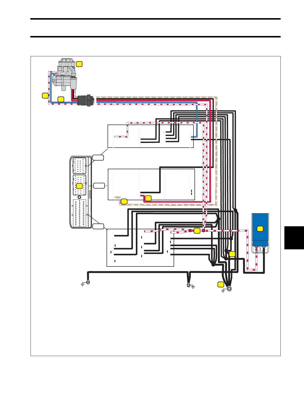
OILING SYSTEM CIRCUIT DIAGRAM
195
9
OILING SYSTEM CIRCUIT DIAGRAM
1.
2.
3.
4.
5.
6.
7.
8.
Oil Injection Pump
EMM
55 V Circuit (WHITE/RED)
Grounds, NEG (BLACK)
EMM to Oil Solenoid (BLUE)
Oil Pressure Sensor, +5 V analog (RED)
Oil Pressure Sensor Signal (TAN/WHITE)
Capacitor
18 19 20 21 22 23 24 25
10 11 12 13 14 15 16 17
20 21 22 23 24 25 26 27 28 29
11 12 13 14 15 16 17 18 19
1 2 3 4 5 6 7 8 9 10
1 2 3 4 5 6 7 8 9
1
4
8
20 21 22 23 24 25 26
26 27 28 29 30 31 32 33 34
J2
J1-B
J1-A
1
2
3
4
5
2
1 2 3 4 5 6 7
8 9 10 11 12 13
14 15 16 17 18 19
3
5
6
4
3
7
005358