123
SYSTEM ANALYSIS
FUEL DELIVERY TESTS
6
If the pump does not run:
• The EMM controls power to the fuel pump (pur-
ple/black wire). Check voltage at pin 1 of fuel
pump connector. Voltage should be 12 V when
KEY is first ON, when fuel pump test activated,
or when outboard is cranking or running.
• Use an ohmmeter to check continuity between
pin 2 of fuel pump connector and ground.
• Refer to Circulation Pump Resistance Test
on p. 181.
If the pump runs:
• Refer to Fuel System Pressure Test on
p. 178.
• Refer to Running Fuel System Tests on
p. 123.
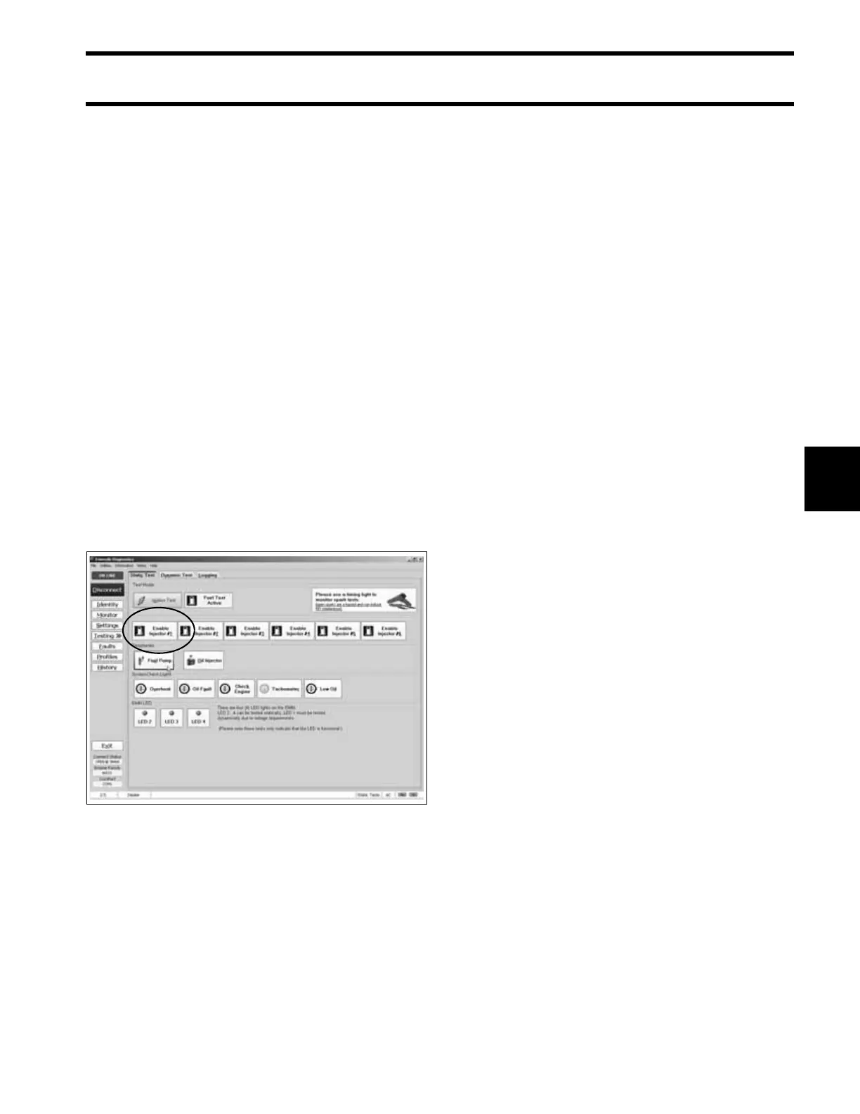
Fuel Injector Static Test
Use the Evinrude Diagnostics software Fuel Injec-
tor Static Test to activate each fuel injector. Listen
for an audible “click” from each injector when it is
actuated. If the injector activates, the EMM and
injector circuits are not at fault.
IMPORTANT: This test is operating the injectors
with 30 V on the system voltage (55 V) circuit. The
start assist circuit (SAC) of the EMM converts bat-
tery voltage (12 V) to 30 V of system voltage. Bat-
tery must be fully charged and connections must
be clean and tight. Injector activation should be
carefully confirmed.
Results:
No injectors actuate:
• Use the Monitor screen of the diagnostics soft-
ware to make sure voltage is present on the
system voltage circuit.
• Refer to Running Fuel System Tests on
p. 123.
Some injectors actuate; some do not:
• Test the resistance of individual injector circuits
between the injector connector and injector con-
trol wire at the EMM.
• See Fuel Injector Resistance Test on p. 180.
All injectors actuate:
• Refer to Running Fuel System Tests on
p. 123.
Running Fuel System Tests
Run or crank the outboard.
Use the Evinrude Diagnostics software Monitor
screen to check system voltage. If voltage is low,
or drops as RPM increases, refer to Stator Volt-
age Output Test on p. 136.
Use an inductive timing light to monitor the injec-
tor control wire (connector pin 2) for each injector.
Make sure the pickup is attached to only one wire.
Flashes on the timing light indicate current in the
circuit is being switched by the EMM. The
Dynamic Tests screen allows the control signal to
be turned off to a particular injector.
IMPORTANT: Some timing lights may not flash
consistently at cranking speeds. Always check the
orientation of the timing light pickup and the oper-
ation of the timing light.
Static Tests Screen 006813