326
GEARCASE – STANDARD ROTATION
DRIVESHAFT SHIMMING
with end of threads. Tighten locking ring on pre-
load screw.
Rotate the driveshaft several revolutions to seat
bearings.
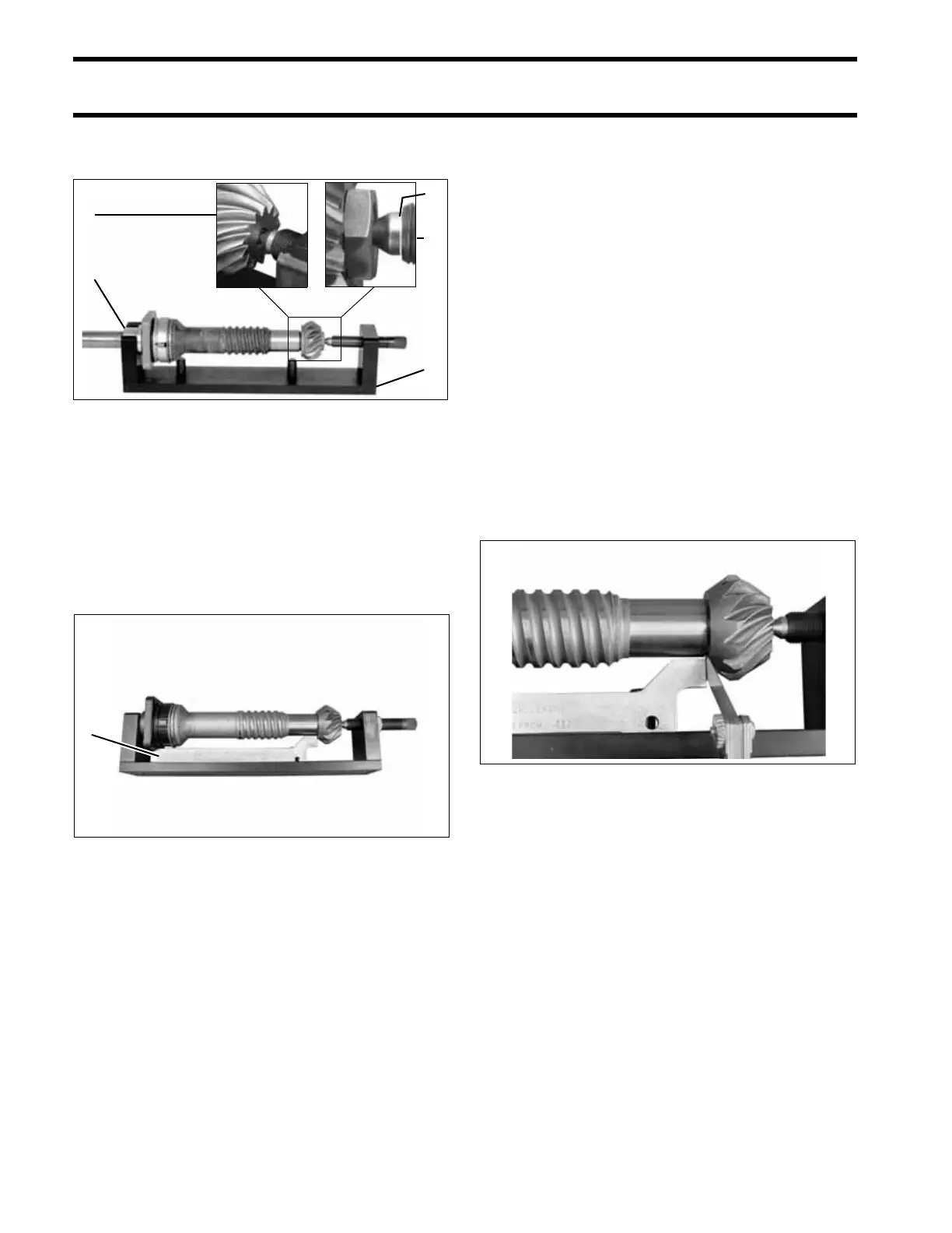
Lay the tool base on its side. Position the shim
gauge bar against guide pins of the tool base.
Check squareness of the bearing housing mount-
ing surface by holding the shim gauge bar against
the pinion while rotating just the bearing hous-
ing. Use a feeler gauge to measure clearance
between the gauge bar and the bearing housing
between each pair of screw holes. Replace the
bearing housing and repeat check if variance is
greater than 0.004 in. (0.010 mm).
Check squareness of the pinion to the driveshaft.
Hold the shim gauge bar against the bearing
housing (between the screw holes) while rotating
just the driveshaft and pinion assembly. Mea-
sure clearance between the gauge bar and the
pinion at several locations. If variance is greater
than 0.002 in. (0.050 mm) replace the pinion or
driveshaft, as necessary, and repeat check.
Subtract the average clearance measurement
from 0.020 in. (0.508 mm) to determine the cor-
rect shim thickness required. Select the fewest
number of shims to achieve the correct thickness.
Remove the driveshaft from the tool and add the
required shims between the bearing housing and
the thrust washer.
IMPORTANT: Use extreme care when remov-
ing bearing housing to avoid damaging the seals.
Use Driveshaft Seal Protector, P/N 318674.
Check clearance again. The measurement
between the gauge bar and pinion should be
0.020 in. (0.508 mm).
“S2” TYPE GEARCASE
Remove the shimming screw and pinion from the
driveshaft.
IMPORTANT: Make sure shimming screw is not
installed in assembled gearcase.
“O”, “L”, “L2”, “M” AND “M2” TYPE
G
EARCASES
Remove the nut and pinion from the driveshaft.
Discard the nut.
1. “S2” Type Gearcase - pinion shimming bolt
2. “O”, “L”, “L2”, “M” and “M2”, Type Gearcases -
pinion nut
3. Collar
4. Tool base
5. Groove
COA3566
DSC00326
005415
1. Shim gauge bar 005416
5
2
4
1
3
1
005417