DTP CrossPoint 84 Series Matrix Switchers • Matrix Software 93
Switcher-to-output mixer block (see figure40,
G
on page80)
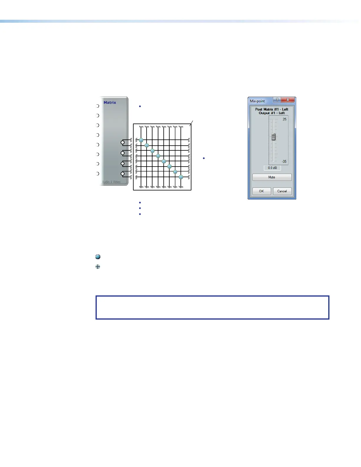
The switcher-to-output mixer block (see figure46) sends audio from the AV matrix block to
the output. It is an array of points where the output of the AV matrix can be mixed into the
output of the DSP. The block provides a way to mute and unmute the output of the AV block
onto the path to the physical audio connectors. The mix-points are unmuted by default.
Unmuting effectively mixes the inputs into the audio outputs at the level set in the left and
right mix controls.
Switcher-to-output
Mixer
}
}
Mic Inputs
Virtual Returns
}
Audio Outputs
1 through 4
Virtual
Send Bus
11
1111
1111
33
3333
3333
44
4444
4444
22
2222
2222
Figure 46. Switcher-to-output Mixer Block and Mix-point Dialog Box
To mute or unmute an input, double-click one of the mix-points (
1
) to open a mix-point
dialog box. Click the Mute button (
2
) in the dialog box to unmute or mute the applicable
input. The appearance of the mix-point indicates the input connection status as follows:
Unmuted
Muted
The mix-point dialog box features a fader control that provides a mix (level) adjustment with
a gain range of -35 dB to +25 dB in 0.1 dB increments. Click and drag the fader (
3
) or
click in the dB field (
4
) and type a value. The default setting is unity gain (0 dB).
TIP: If you have an audio signal is output on the virtual bus and looped around back
to the virtual input, mute the audio output by the AV block in these mix-points to
prevent the unprocessed signal from being output along with the processed audio.
42