DTP CrossPoint 84 Series Matrix Switchers • Matrix Software 96
NOTES:
• Unlike from line inputs 1 through 4 (typically program audio), more than one mic,
virtual return, or expansion port audio input can be mixed into a single audio output.
• The message Input is muted! in figure48,
5
on the previous page indicates that
Mute is selected in the mic/line input gain control block. This message can appear
ONLY for mix-points in the mic-to-output mixer block.
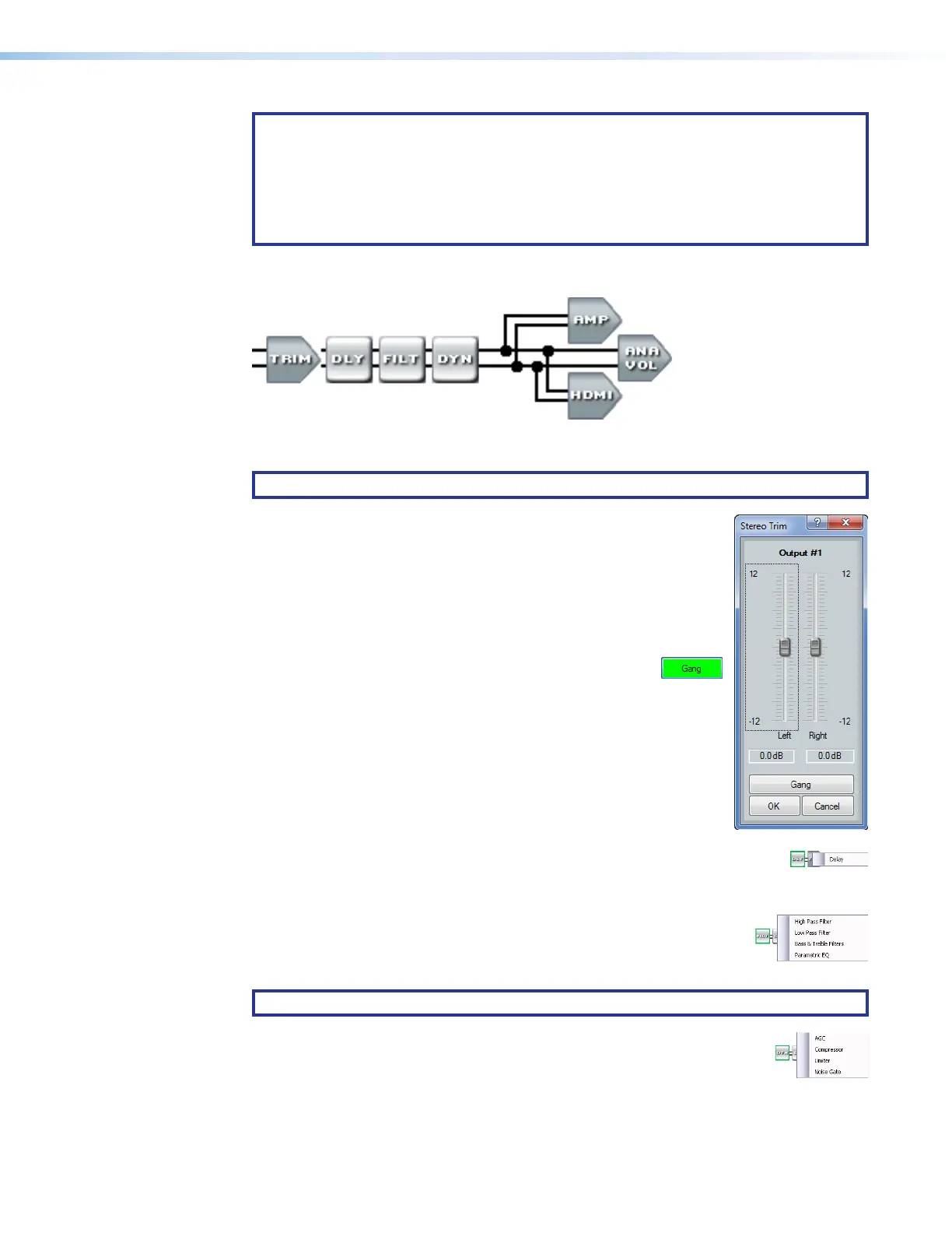
Output signal processor chain (see figure40,
K
on page80)
The output signal processor chain makes adjustments to mixed program and microphone
audio, before it is output to the selected speakers or other audio devices.
NOTE: * This output 1 amplifier block is not present on non-IPCP models.
Trim control block — The always-present trim control provides
11
1111
1111 11
1111
1111
22
2222
2222 22
2222
2222
33
3333
3333
left and right controls to adjust the audio level of each output through
a range of -12 dB to +12 dB to ensure that there is no noticeable
volume difference among sources.
Click and drag the desired fader (
1
) or click in the dB field (
2
) and
type a value. The meter value displayed in green shows the signal level
in dBFS.
3
Gang button — Select to tie the left and right fader
controls together. Ganged faders move together at
relative levels to the top or bottom of their travel. If one fader
reaches the limit of its travel first, it retains that position while the
other fader continues to travel. When the ganged faders travel in
the reverse direction, the fader that was at its limit reverts to its
position relative to the other fader.
Delay block — The delay processor block, when inserted, provides a means
to delay the audio signal to sync it to video. The delay processor block is
identical to as described for the Line audio Delay block, on page 87.
Filter block — The filter processor block, when first inserted, provides
one of four filter selections; additional filters can be then be added. The
available filters and adding additional filters are identical to as described
for the Line audio Filter block, on page 86.
NOTE: Selecting Bass & Treble Filter inserts two separate filters.
Dynamics block — The dynamics processor block, when inserted, each
provide one of four dynamic processors. The available processors are
identical to as described for the Line audio Dynamics block, on page 86.