DTP CrossPoint 84 Series Matrix Switchers • Matrix Software 86
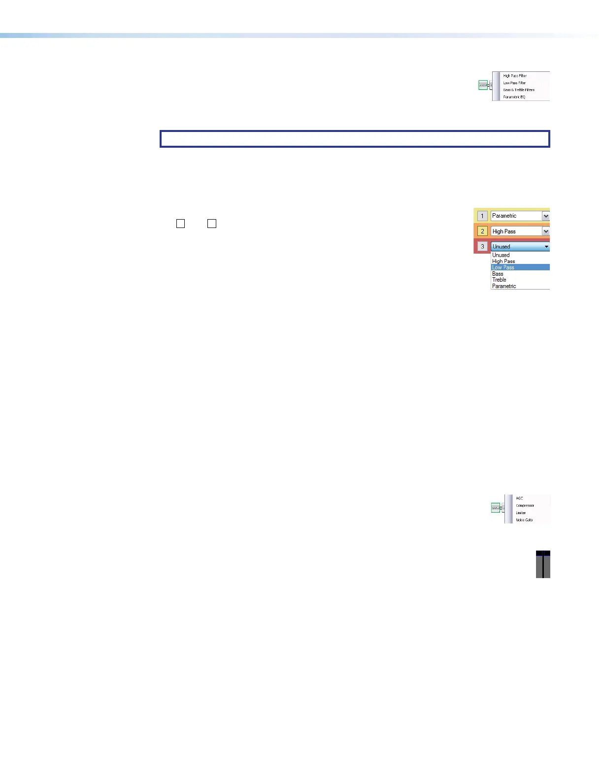
Filter block — The filter processor block, when first inserted, provides
one of four filter selections; additional filters can then be added. A filter
attenuates (removes) or boosts a range of frequencies from an audio
waveform, while passing other frequencies. Click the desired filter to
select it.
NOTE: Selecting Bass & Treble Filter inserts two separate filters.
Additional filters, for a total of up to three filters, can then be added by double-clicking the
processor block. Additionally, the frequency range of each filter can be changed in the
dialog box, customized to the filter, that can be accessed by double-clicking the processor
block.
To add a second or third filter to the filter block, select the desired filter in
11
1111
1111
22
2222
2222
33
3333
3333
44
4444
4444
the
2
and
3
drop-down boxes in the dialog box.
The following filters are available:
1
High pass filter — A high pass filter passes a band of
frequencies extending from a specified cutoff frequency (greater
than zero) up toward the high end of the frequency spectrum. All
frequencies above the specified cutoff frequency are allowed to
pass, attenuating all frequencies below. The default cutoff is 100 Hz.
2
Low pass filter — A low pass filter passes a band of frequencies extending from a
specified cutoff frequency (less than infinite) down toward the low end of the frequency
spectrum. All frequencies below the specified cutoff frequency are allowed to pass,
attenuating all frequencies above. The default cutoff is 10 kHz
3
Bass and treble filters — Also known as shelving or tone filters, the separate
bass and treble filters give the ability to cut or boost gain evenly above or below a given
frequency, with the end-band shape giving the visual appearance of a shelf. These filters
are typically applied to program material, and are expressed as bass and treble control.
The default bass frequency is 100 Hz and the treble default is 8 kHz.
4
Parametric equalizer filter — A parametric equalizer is a variable equalizer that
offers control of all parameters, including amplitude (boost or cut — the amount of gain
(boost) or gain reduction (cut) that is applied at a given frequency), center frequency
(frequency), and bandwidth (Q). This allows the user to control the amplitude of each
band, shift the center frequency, and widen or narrow the affected area.
Dynamics blocks (2) — The two dynamics processor blocks, when inserted,
22
2222
2222
11
1111
1111
33
3333
3333
each provide one of four dynamic processors. A dynamic processor alters
the dynamic range of an audio signal, the difference between the loudest to
the quietest portions of the signal above the noise floor of the system.
Dynamic range can either be increased using an expander (noise gate) or reduced using a
compressor. Click the desired dynamics processor to select it or to view a live audio
meter as shown at right.
The parameters of each processor can be changed in the dialog box, customized to
the processor, that can be accessed by double-clicking the processor block.
1
Automatic gain control (AGC) — AGC adjusts the gain level based upon the strength
of the incoming signal to achieve a more consistent volume. Above a set threshold,
weaker signals receive more gain to reach a user-defined target level; stronger signals
receive less gain or no gain at all.
A window range is also applied above and below the target level. When the signal
reaches the window, gain control starts scaling in a linear fashion toward the target level
to achieve smoother results.
The default threshold is -40 dB. The default target level is -10.0 dB. The default gain
and window are 12.0 dB.
Dynamic blocks drawing