DTP CrossPoint 84 Series Matrix Switchers • Matrix Software 85
• Multi-Channel — The detected format is any compressed or encoded digital
audio format, such as Dolby or DTS multi-channel.
• Multi-channel input audio does not pass through the DSP regardless of
selected Audio Format (see item
3
in Line audio input signal controls on
page84). Gain, mute controls, and meters are disabled and unavailable for
operation throughout the DSP.
• Multi-channel input audio passes to an HDMI or DTP output, bypassing the
DSP, if the Output Signal Source control in the Volume block of that output
is set to Original (see item
6
in Output signal processor chain, Volume
controls on page97).
• Analog input audio passes through the DSP to any output when Audio Format
(
3
) is set to Analog or Auto.
See item
5
for interaction with the Audio Format drop-down box.
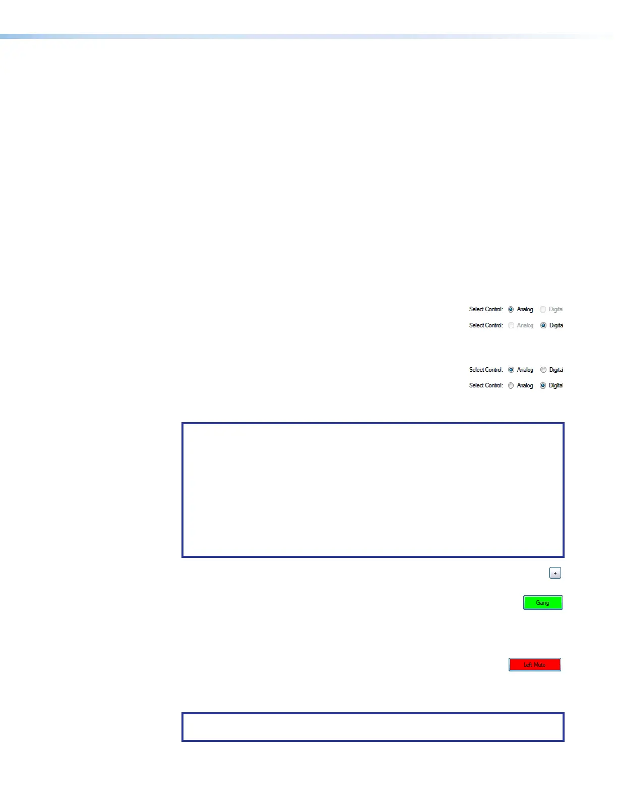
5
Select Control indications and radio buttons (see the Line audio input signal
controls drawing) — These buttons indicate the audio, Digital or Analog, that is
adjusted by this control block. This control reacts to the Audio Format (
3
) control as
follows:
• Audio Format (
3
): Analog —
• Audio Format (
3
): Digital —
• Audio Format (
3
): Auto — The software automatically selects the radio button
dependent on the Detected Format: field (
4
) display as follows:
• Detected Format (
4
): None or Multi-Channel —
• Detected Format (
4
): LPCM —
You can manually select a radio button only when the Audio Format drop-down box
(
3
) is set to Auto. Select Digital or Analog to override the selected control.
NOTES:
• Setting the analog gain without a signal present may have a real-world
application. For example, if you have a consumer audio component, a gain
setting of 11.8 dB (consumer line level of -10dBV; pro line level of +4dBu;
conversion factor from dBV to dBu = 11.8 dB) brings its line level up to pro line
level or you can see the suggested setting if you insert a building block for a
consumer audio product (see Signal Path Building Blocks on page118).
• Setting the digital gain without a signal present is less likely. If you know the
general level of your source material you can attempt this but Extron does not
recommend doing so.
6
Polarity buttons (see the drawing on page 84 — Select to flip the polarity
of the audioconnectors (+/tip and -/ring) to easily correct for miswired connectors.
7
Gang button (see the drawing) — Select to tie the fader and mute controls
together. Ganged faders move together at relative levels to the top or bottom
of their travel. If one fader reaches the limit of its travel first, it retains that position while
the other fader continues to travel. When the ganged faders travel in the reverse
direction, the fader that was at its limit reverts to its position relative to the other fader.
8
Mute buttons (see the drawing) — Select to separately mute and
unmute the audio channels. If you mute both channels, audio is completely silent on
that input. When one or both channels are muted, one or two red indicators in the block
turn on. The mute controls are common to both digital and analog signals.
NOTE: When the left and right channels are ganged, either Mute button mutes and
unmutes both channels.
Gang button