DTP CrossPoint 84 Series Matrix Switchers • Matrix Software 87
2
Compressor (see the Dynamics blocks drawing on the previous page) — The
compressor regulates the level of the input signal by reducing, or compressing, the
dynamic range of the signal above a specified threshold. The input-level-to-output-level
ratio of the signal determines the reduction in the dynamic range beyond the threshold
setting. For example, with a ratio setting of 2:1, for every 2 dB of input the compressor
outputs 1 dB of gain.
Compression is commonly used to keep mic levels within an acceptable range for
maximum clarity. A compressor make softer sounds louder either by reducing the
dynamic range and then raising the output level of the compressor (referred to as
make-up gain), or by increasing the input signal and then preventing clipping by
reducing the louder portions of the signal. This has the effect of making louder portions
of a signal softer. Compression also can be used, similar to a limiter, to protect a system
or a signal chain from overload.
The default threshold is -30 dB. The ratio is 2.0:1.
3
Limiter (see the drawing) — The limiter regulates the level of the input signal by
severely restricting its dynamic range above a specified threshold. The limiter prevents
clipping and protects a system against component or speaker damage. The limiter
is closely related to the compressor but applies a much higher compression ratio, in
excess of 20:1 (often expressed as ∞:1) and with a high threshold setting (default is -10
dB, close to clipping). The ratio cannot be changed.
4
Noise gate (see the drawing) — The noise gate is an expander, expanding the
dynamic range of a signal below a specified threshold. To simplify, it makes soft signals
softer, effectively removing background noise while allowing a stronger signal, above the
threshold, to pass. Using a high ratio of 20:1, the expander closes the audio path below
the threshold, eliminating background noise, opening the path above the threshold to
allow signal to pass; hence the term noise gate.
The default threshold is -65 dB. The ratio is 20.0:1.
Delay block — The delay processor block, when inserted, provides a means
to delay the audio signal to sync it to video. The processor can delay the audio
using either time or distance in feet or meters between the video display and audio
speakers, as a determiner. The default delay, when inserted, is at 100 ms using the time
function. The settings of the delay block can be changed in the dialog box that can be
accessed by double-clicking the processor block. When you select either Feet or Meters,
you can also specify a temperature, in either degrees Fahrenheit or degrees Celsius The
processor calculates the change in speed of sound for the specified temperature.
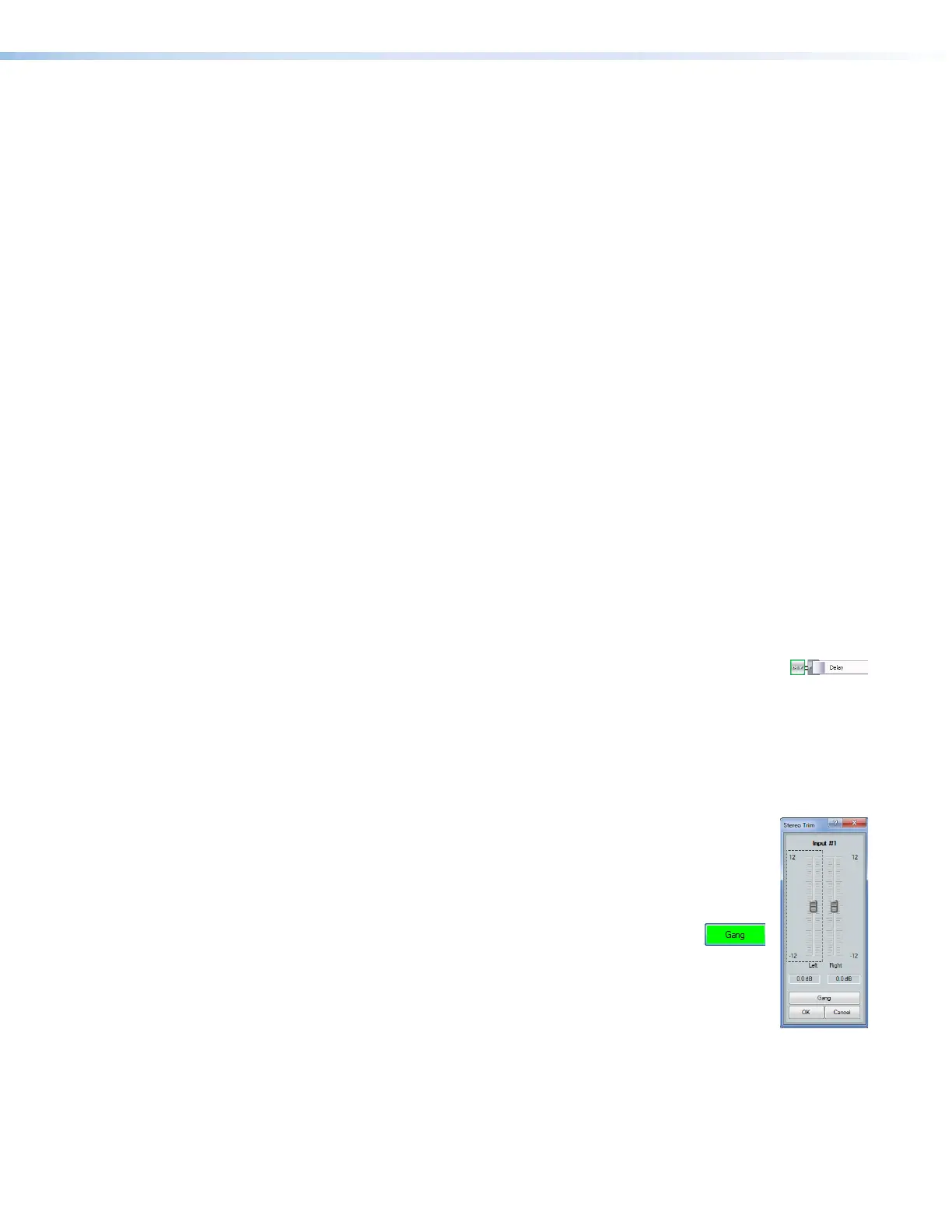
Trim control — The always-present trim control provides separate left and
22
2222
2222
11
1111
111111
1111
1111
33
3333
3333
right input channel faders for fine adjustment with a gain range of -12 dB to
+12 dB in 0.1 dB increments. The default setting is unity gain (0.0 dB).
Click and drag the desired fader (
1
) or click in the dB field (
2
) and type a
value.
3
Gang button — Select to tie the left and right fader controls
together. Ganged faders move as described for the Gang
button (
7
) on page85 .