DTP CrossPoint 84 Series Matrix Switchers • Matrix Software 88
Mic/line input signal controls (see figure40,
B
on page80)
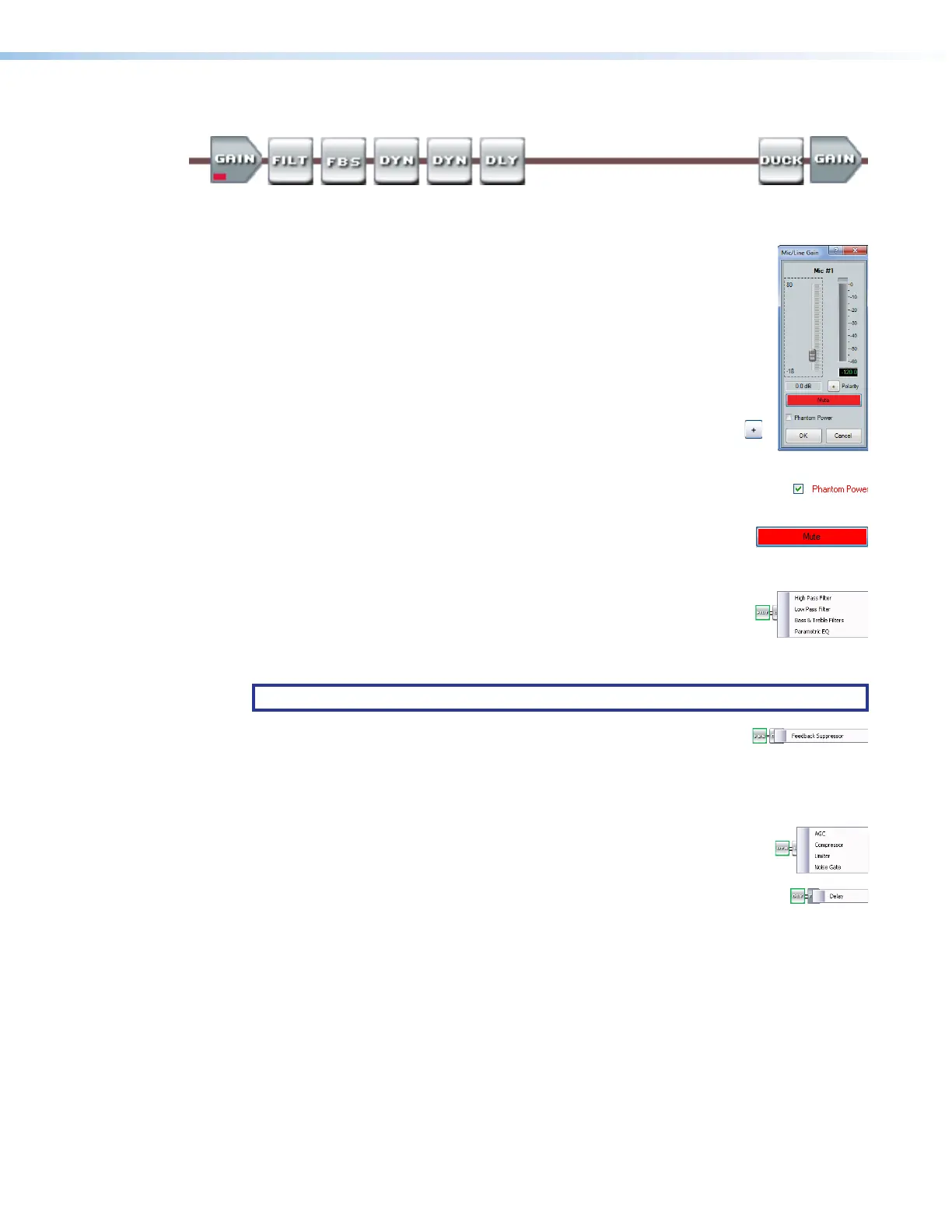
The mic/line input signal processor chain makes adjustments to microphone or line level
audio material, such as a multimedia presentation, before it is mixed with program audio.
Gain control — The always-present gain control provides a single
11
1111
1111
33
3333
3333
22
2222
2222
44
4444
4444
55
5555
5555
long-throw fader with a gain range of 0 dB to +80 dB, adjustable in 1 dB
increments, with a level setting readout below the fader.
A gain range from 0 to +10 dB accommodates a line level signal, typically
from a wireless microphone receiver with a line level output.
Above +10 dB, the input switches to a mic level input.
Click and drag the fader (
1
) or click in the dB field (
2
) and type a value.
The meter value displayed in green shows the signal level in dBFS.
3
Polarity buttons —Select to flip the polarity of the wires
connected to the audio connectors (+/tip and -/ring) to easily
correct for miswired connectors.
4
Phantom Power check box — Click to toggle +48 VDC phantom power
on and off, typically to power a condenser mic.
5
Mute button — Select to silence and unmute the mic audio.
If you mute the audio, it is completely silent on that input. When the
audio is muted, a red indicator in the block turns on.
Filter block — The filter processor block, when first inserted, provides
one of four filter selections; additional filters can be then be added. The
available filters and adding additional filters are identical to as described
for the Line audio Filter block, on page 86 (except that up to five filters
total can be selected for this block).
NOTE: Selecting Bass & Treble Filter inserts two separate filters.
Feedback suppressor block — The feedback suppressor processor
block, when inserted, detects feedback on a live microphone channel,
and uses a set of fixed and dynamic filters to counteract the frequency peaks at the
detected feedback frequencies. You may possibly achieve an additional 3 dB to 9 dB of mic
gain where feedback would have otherwise prevented these levels.
Dynamics blocks (2) — The two dynamics processor blocks, when inserted,
each provide one of four dynamic processors. The available processors are
identical to as described for the Line audio Dynamics block, on page 86.
Delay block — The delay processor block, when inserted, provides a means
to delay the audio signal to sync it to video. The delay processor block is
identical to as described for the Line audio Delay block, on page 87.