DTP CrossPoint 84 Series Matrix Switchers • Matrix Software 89
Ducking block — The ducking processor block, when
11
1111
1111
22
2222
2222
33
3333
3333
55
5555
5555
44
4444
4444
66
6666
6666
inserted, pr
ovides a means to duck, or lower the level of
one or more input signals (ducking targets, such as
microphones, the program material, or audio input on
the virtual bus) when a specified source must take
precedence. The inserted ducking processor block
ducks the targets when the processor detects a signal
from the ducking source. Ducking lasts for the duration
of the interrupting signal (plus hold and release time)
and restores the original level of the ducked mic once
the other signal has ceased. Ducking is useful when:
•
Pr
ogram material needs to be attenuated in order
to more clearly hear the voice of the narrator.
• One microphone, such as one used by a master
of ceremonies, needs to have priority over other
mics, program material, or both.
• A paging mic needs to attenuate all other signals.
All four ducking processor blocks are controlled via a
common dialog box that opens when you select to
configure any of the ducking blocks. All empty ducking processor blocks have no ducking
source or target settings by default.
In some cases, multiple levels of ducking may be required, enabling an input source to take
precedence over all but one other input.
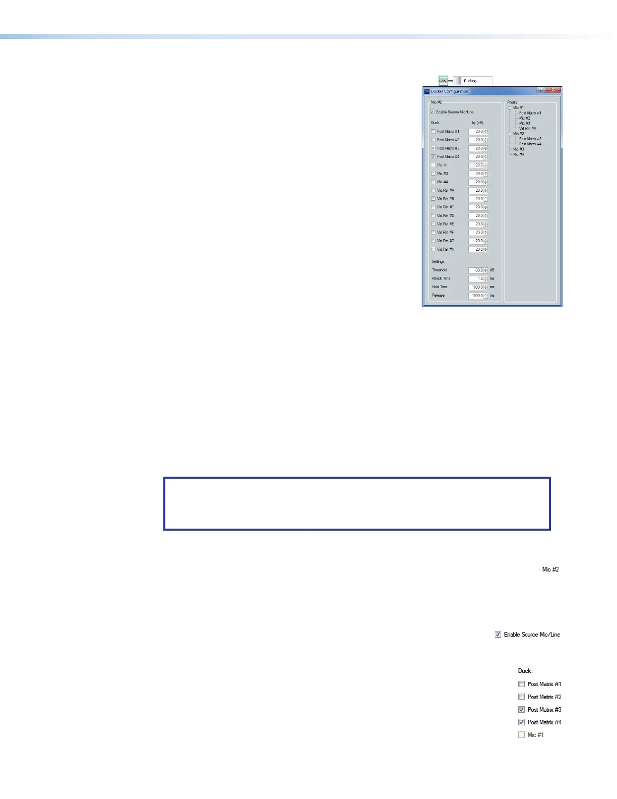
In the priority tree on the right side of the figure above, post-matrix 1, mic inputs 2 and 3,
and virtual return A are set to duck when mic 1 has a signal above the ducking threshold.
Mic2 is set to duck post matrix 3 and 4. Since mic 1 has previously been set to duck mic 2,
mic 1 is disabled to prevent contradictory priorities.
The inputs are arranged by their priority status. Mic 1 has all other ducked inputs under
it; therefore, if a signal is detected, it triggers mics 2 through 4 to duck. If mic 2 detects a
signal and there is no signal on mic 1, mic2 triggers mics 3 and 4 to duck. However, if the
mic1 signal exceeds the threshold, it then ducks all inputs including mic 2.
NOTE: Ducking attenuation is not additive. When an input target is ducked,
regardless of how far down the priority line it is, the maximum attenuation is that set
for the individual input and virtual send in the “by (dB):” column near the center of
the dialog box.
See Ducker Priority Tutorial starting on page123 for a more detailed examination of
priority.
1
Current source indicator (see the Ducking block above) — Shows the input
selected is the ducking source. Ducker settings affect the input channel shown here.
When a ducker dialog is opened for a channel, the current source defaults to that
channel. The current source can also be selected via the priority tree (see Priority,
5
on the next page).
2
Enable Source Mic/Line check box — When checked, ducking is
is enabled for the current source and the ducker processor block is lit. When cleared,
ducking is disabled for the current source and the ducker processor block is unlit.
3
Duck: (targets) — Shows all potential input targets. Only checked inputs
are ducked. The current source is not available as a target (a source cannot
duck itself). If the current source has been designated as a target of
another input channel, that input channel is not available (a target cannot
be the source).
Ducking block