A1400 AIR RDT 106 532119 04 - Rev. C
C
I
108
Lt = Vp X 1,5 + 100
Vp
Lt
87,5
B1
92,5
B
Vp Lt B B1 I C D LC
1100 1750 380 435 1290 215 2740 1750
1200 1900 430 485 1390 215 2940 1850
1300 2050 480 535 1490 215 3140 1950
1400 2200 530 585 1590 215 3340 2050
1500 2350 580 635 1690 215 3540 2150
1600 2500 630 685 1790 215 3740 2250
1700 2650 680 735 1890 215 3940 2350
1800 2800 730 785 1990 215 4140 2450
Vp Lt B B1 I C D LC
1900 2950 780 835 2090 215 4340 2550
2000 3100 830 885 2190 215 4540 2650
2200 3400 930 985 2390 215 4940 2850
2400 3700 1030 1085 2590 215 5340 3050
2600 4000 1130 1185 2790 215 5740 3250
2800 4300 1230 1285 2990 215 6140 3450
3000 4600 1330 1385 3190 215 6540 3650
Translation of the original instructions
ENGLISH
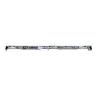
POSITION OF COMPONENTS ON SUPPORT PROFILE
A1400 AIR RDTRIGHT OPENING SINGLE LEAF
Motor 2
Motor 1
Control
Board
Power supply
unit
Emergency
batteries
B = Carriage fixing distance
on the sliding leaf
B1 = Carriage fixing distance
on the sliding leaf
C = Motor position dimension
D = Length of transmission belt
I = Motor / transmission unit centre
distance
LC = Steel cable length
Lt = Length of head section
Vp = Free passage width
100 = mm leaf overlap

 Loading...