Page 12 of 97 PN: 106417-05
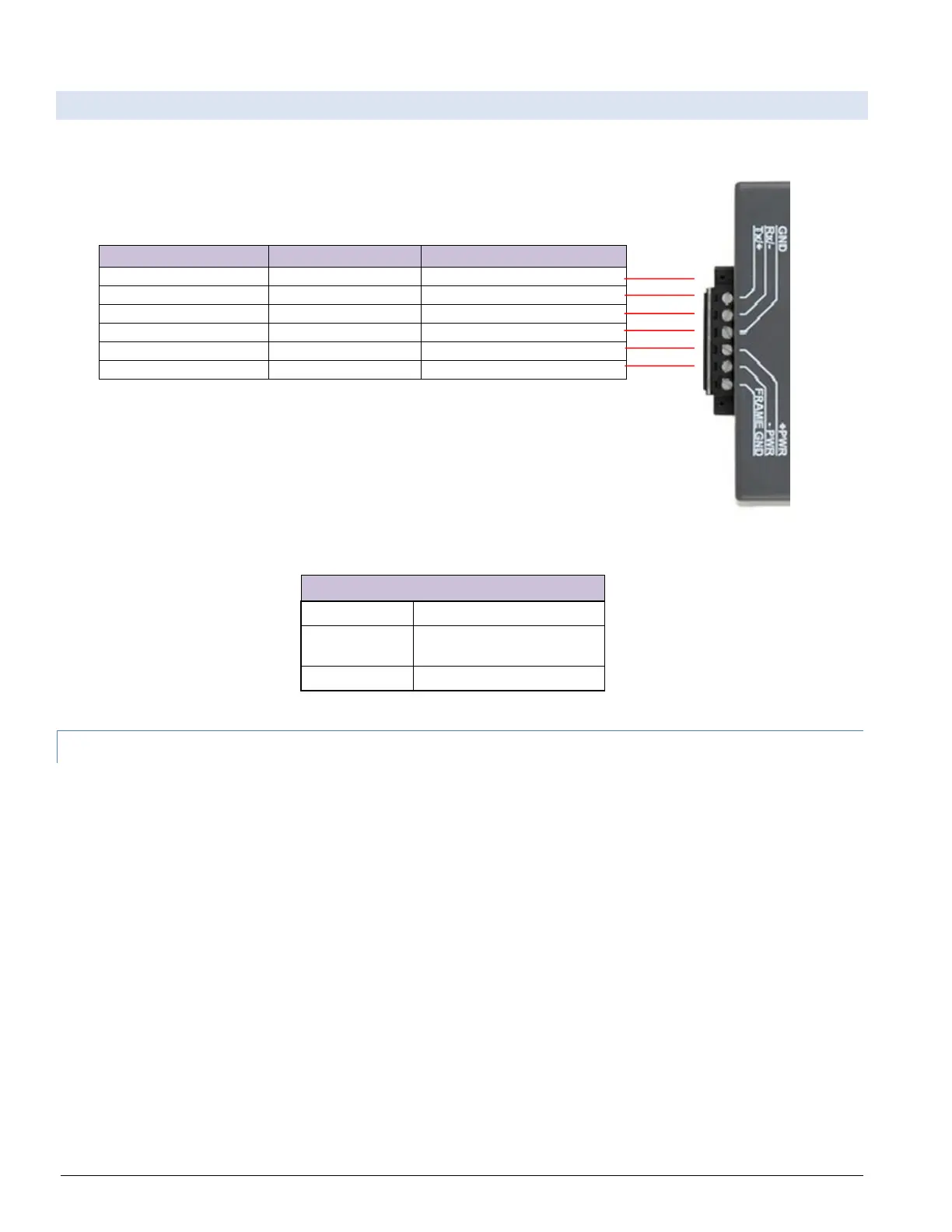
3.2 Wiring to the ProtoNode 6 Pin Connector
• Pins 1 through 3 are for Modbus RS-485 devices. The RS-485 GND (Pin 3) is not typically connected.
• Pins 4 through 6 are for power.
Table 3-1: ProtoNode Pin Assignments
Apply power to ProtoNode as shown below. Ensure that the power supply used
complies with the specifications provided in Section 7.
• ProtoNode accepts either 9-30VDC or 12-24 VAC on pins 4 and 5.
Table 3-2: ProtoNode Power Requirements
3.2.1 Biasing the Modbus RS-485 Device Network
• The ProtoNode has 510 Ohm resistors that can be used to set the biasing. The ProtoNode’s
default positions from the factory for the Biasing jumpers are OFF.
• The OFF position is when the 2 RED biasing jumpers straddle the 4 pins closest to the outside of
the board of the ProtoNode. See Figure 3-2.
• Only turn biasing ON:
o IF the BMS cannot see more than one device connected to the ProtoNode
o AND you have checked all the settings (Modbus COM settings, wiring, and DIP
switches).
• To turn biasing ON, move the 2 RED biasing jumpers to straddle the 4 pins closest to the inside of
the board of the ProtoNode.