EasyManua.ls Logo

FieldServer LonWorks ProtoNode - Apex, Alpine, ASPEN, Phantom-X or Raptor with Panasonic Display

FieldServer LonWorks ProtoNode
97 pages
Print Icon
To Next Page IconTo Next Page
To Previous Page IconTo Previous Page
Loading...
Page 16 of 97 PN: 106417-05
3.4 Apex, Alpine, ASPEN, Phantom-X or Raptor with Panasonic Display
J7
A8
A7
A6
A5
A4
J3
5
4
3
2
1
A 321
V-
BAV+B
MB1
MB2
ECOM
-
BL
OR
GR
OR
BL
WH
VDC
GND
Panasonic GT02 Display
EMS/Boiler to Boiler
Communication Network
(Use CAT5 Cable) RJ45
ENVIRACOM
Communication to
Zone Panel (Use CAT5
Cable) RJ45
ProtoNode
RS485 GND
RS485 -
RS485 +
+ PWR
- PWR
FRAME GND
1
2
3
Apex with Panasonic Display
Type A RJ45 Wiring Notes
1 Wire to Brown
2 Wire to White/Brown
3 Wire to Green
RJ45 Wire
Apex with Panasonic Display
Type B RJ45 Wiring Notes
1 Wire to Brown
2 Wire to White/Brown
3 Wire to Orange
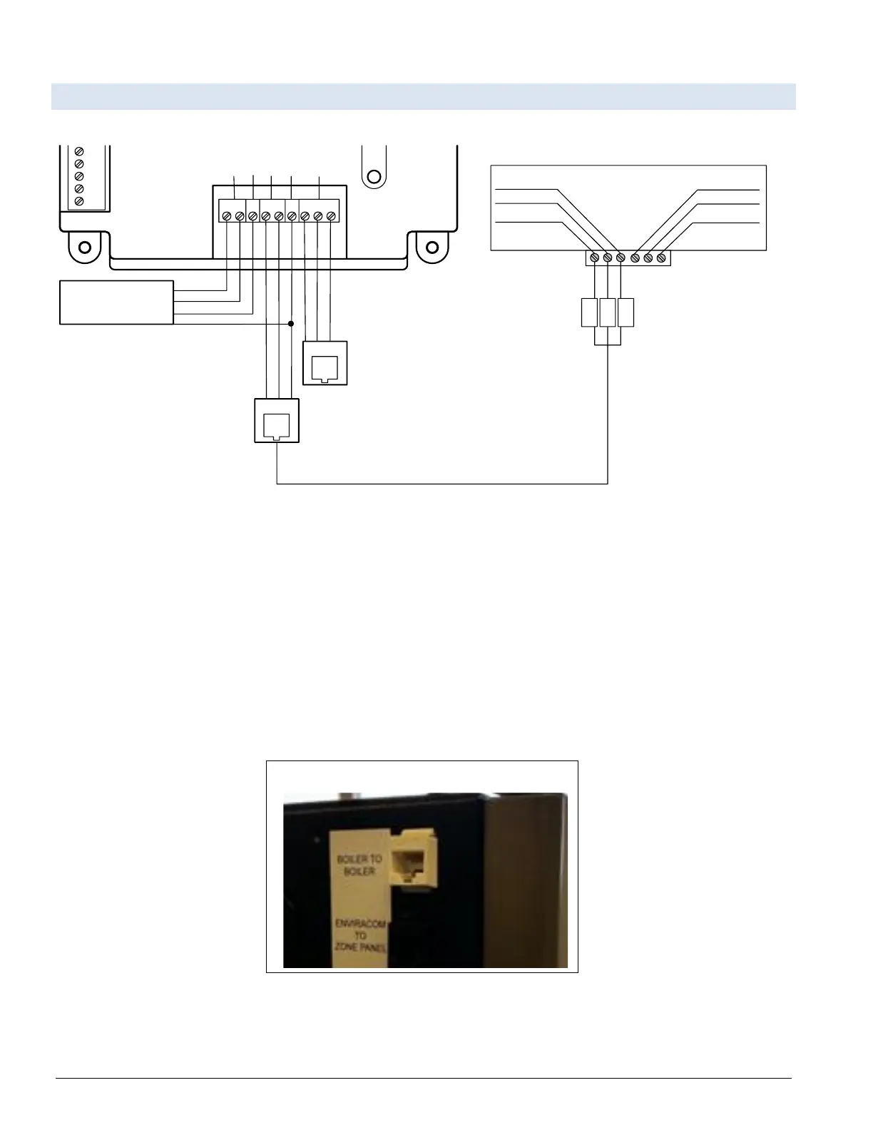
Figure 3-7: Apex, Alpine, ASPEN, Phantom-X or Raptor with Panasonic Display Modbus
RS485 Wiring
The Modbus communication connects to the same RJ45 port that is used by the boiler-to-boiler communication.
Connect one end of the RJ45 cable to the boiler and cut off the other end of the cable to access the individual wires
of the RJ45 cable. Wire the RJ45 cable as shown above.
When wiring to Sage/Sola without the RJ45 cable make the following connections:
Connect MB2’s terminal A (RS-485+) to Pin 1 (RS-485+) on the ProtoNode.
Connect MB2’s terminal B (RS-485-) to Pin 2 (RS-485-) on the ProtoNode.
Connect MB2’s terminal C (ground) to Pin 3 (ground) on the ProtoNode.
Figure 3-8: RJ45 Boiler to Boiler/EMS RJ45 Communication Port on Side of Boiler

Table of Contents

Related product manuals