FIMER_PVS-175-TL A.1 Version_Product manual_EN_RevC-
F
145
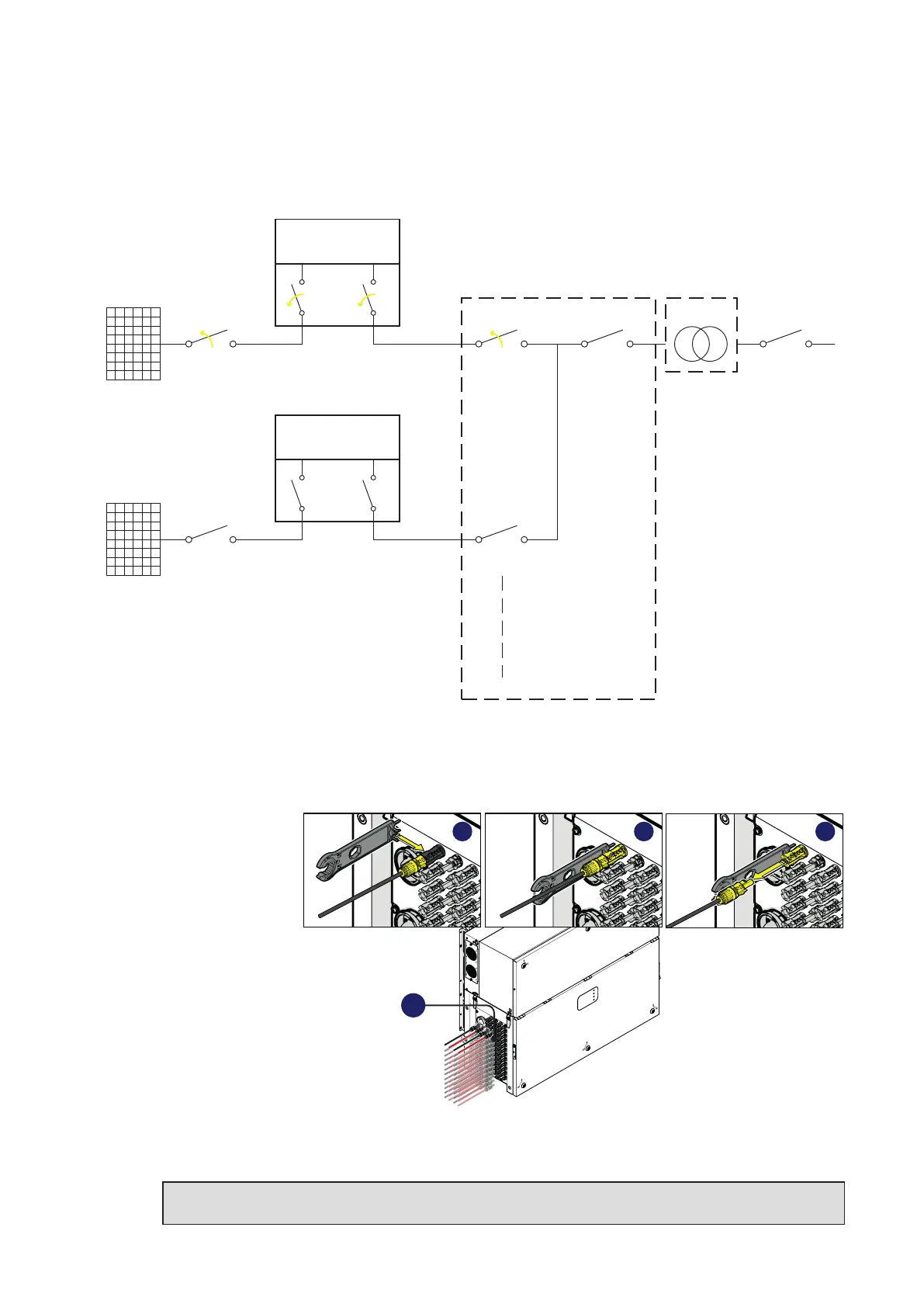
The below picture represents the expected status of the switches in the plant after the
switching operations has been completed.
PV Strings
External DC
Switch
Internal DC
Switches
Internal AC
Switch
INVERTER UNIT
(Unit under service)
PWRMOD
WBOX
OPEN+LOTO
PV Strings
External DC
Switch
Internal DC
Switches
Internal AC
Switch
INVERTER UNIT
PWRMOD
WBOX
External LV
AC Switch
External Main LV
AC Switch
External LV
AC Switch
LV Distriubution
Panel
MW Switch
LV/MW
Transformer
OPEN+LOTO
OPEN
+
LOTO
OPEN
+
LOTO
9. Remove the DC quick fit connectors (18) from wiring box (02)
• Using the
current clamp
check the
absence of
current on DC
side, measure
each positive
and negative
DC input string
cables (check
the correct
setting of the
current sensor).
• Remove all
quick fit DC
connectors (18)
from the wiring box (02), using the dedicated disconnect tool. To avoid mechanical interferences,
use a cable tie to collect the disconnected cables.
NOTE – D It is highly recommended to put labels on each cable in order to easily reconnect
them to the correct connectors once completed the service activities.
PVS
18
A B C