FIMER_PVS-175-TL A.1 Version_Product manual_EN_RevC-
F
148
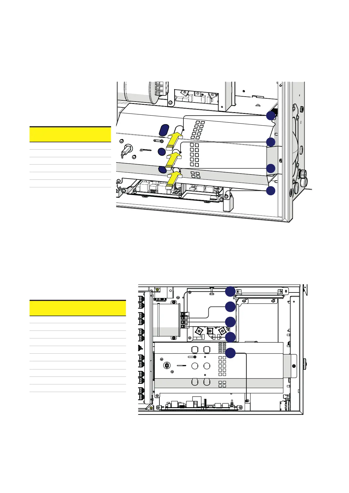
are designated as visually inspection holes, to make sure the electrodes of the voltage detector are
touching the main AC screws on the AC connection busbar (22).
Check
sequence
First
point
Second
point
Check #1 R ( L1) PE
Check #2 S (L2) PE
Check #3 T (L3) PE
Check #4 R ( L1) S (L2)
Check #5 S (L2) T (L3)
Check #6 T (L3) R ( L1)
13. Voltage absence test on AC capacitor (wiring box)
•
Check there is no voltage on the AC capacitor’s terminals, measuring between all points, as indicated
in table below
Check
sequence
First
point
Second
point
Check #1 R (L1) PE
Check #2 S (L2) PE
Check #3 T (L3) PE
Check #4 N PE
Check #5 R (L1) S (L2)
Check #6 S (L2) T (L3)
Check #7 T (L3) R (L1)
Check #8 R (L1) N
Check #9 S (L2) N
Check #10 T (L3) N
PE
T
S
R
R
T
PE
N
S