FIMER_PVS-175-TL A.1 Version_Product manual_EN_RevC-
F
62
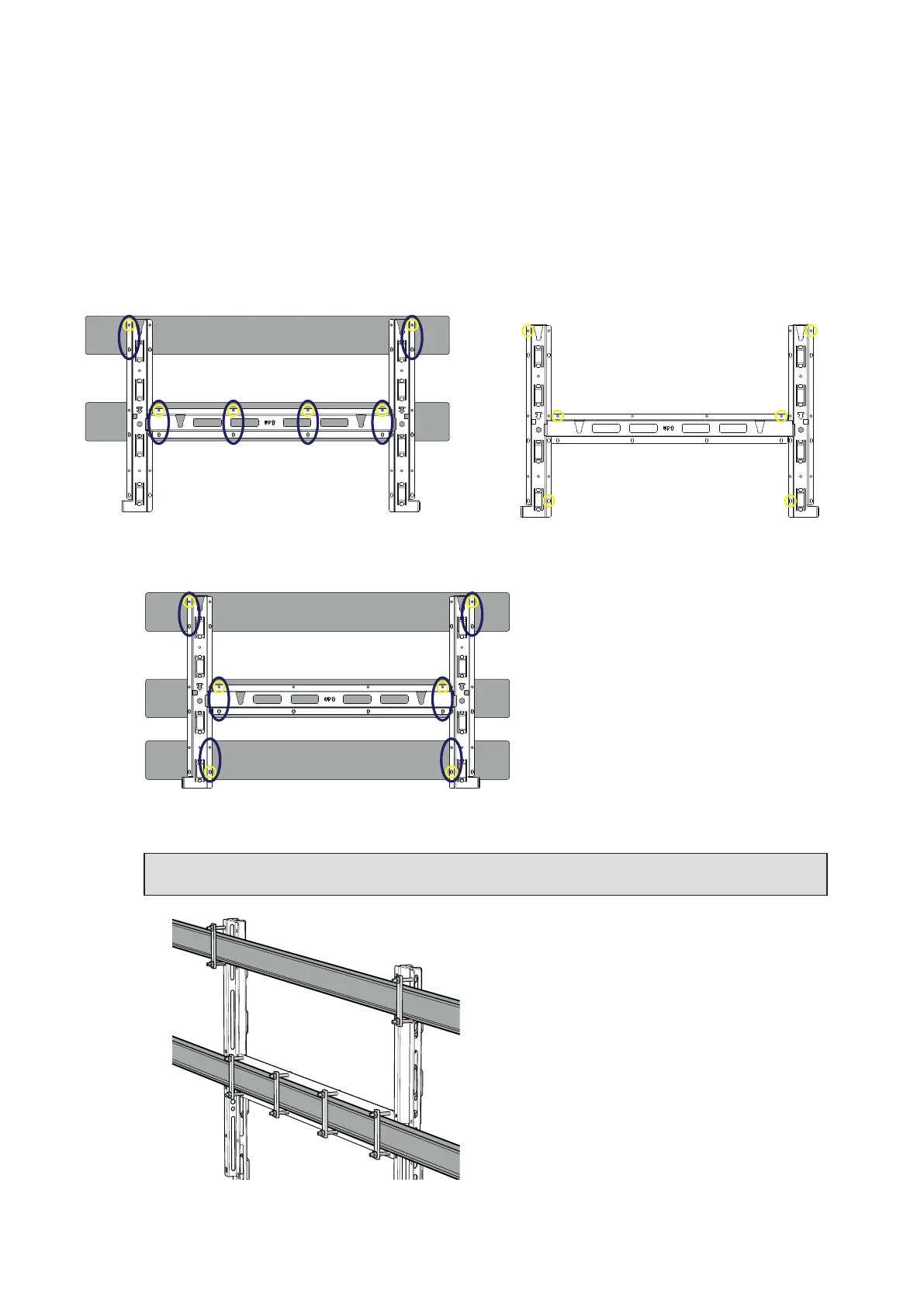
•
It is an installer’s responsibility to choose an appropriate number and distribution of attachment
points. The choice must be based on the type of support (wall, frame or other support), the type of
anchors to be used, and their ability to support at least 4 times the inverter’s weight (4x153Kg=612Kg
for all models).
• Attach the bracket (03) to the support with at least 6 attachment screws (shown in RED) or at least
6 frame fixing bracket for frame mounting (shown in BLUE).
•
Depending on the type of anchor chosen, drill the required holes to mount the bracket (03).
The pictures shown the recommended minimum fixing point depending to type of support.
Wall mounting minimum fixing points
Frame mounting (2 supports) minimum fixing
points
Frame mounting (3 supports) minimum fixing
points
NOTE – D In case of use of “frame fixing brackets” (see picture as example) it will be possible
to fix the bracket to the frame structure without drilling any additional holes.
• Fix the bracket (03) to the support.