FIMER_PVS-175-TL A.1 Version_Product manual_EN_RevC-
F
73
33
30
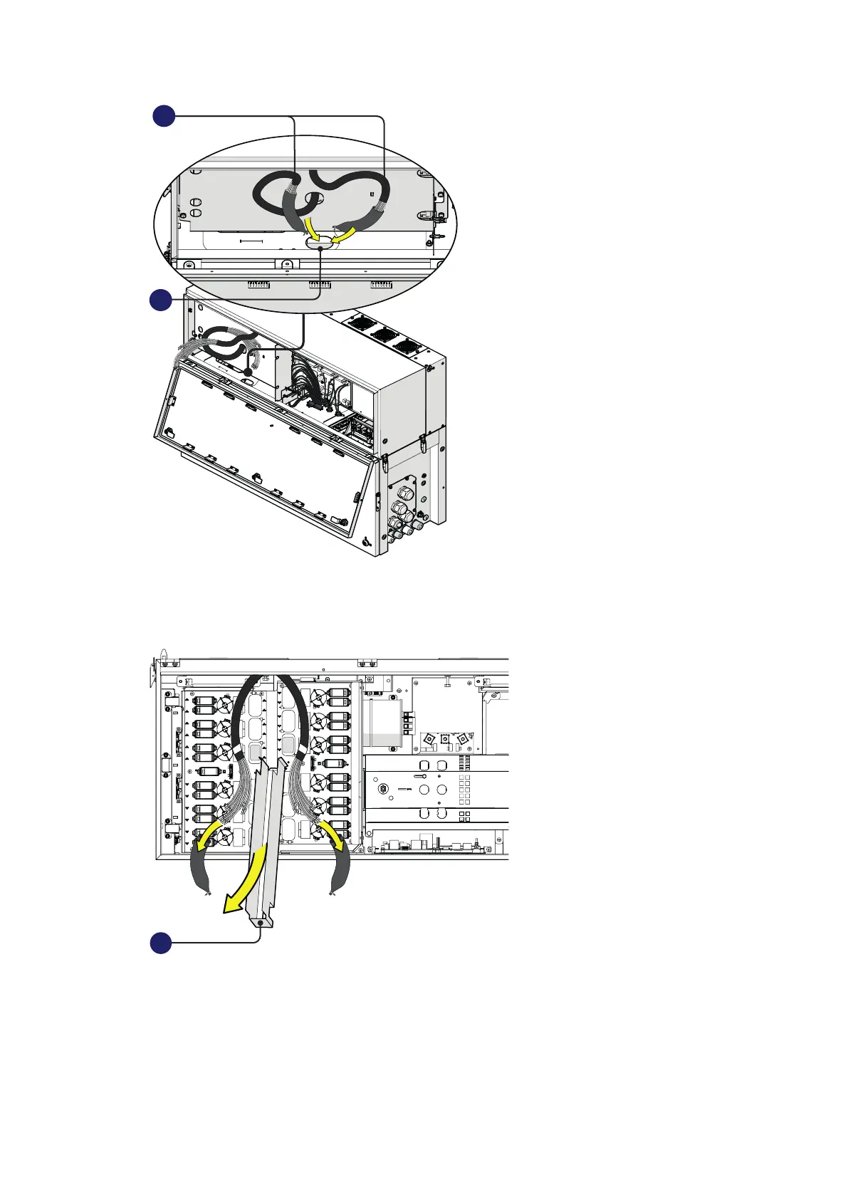
• Close the power module cover (06) and open the wiring box cover (07)
•
• Remove the cable sheathing from the DC interface cables (33) and the DC cable duct (22) from the
DC surge arrester plate (21).
22
• Connect all DC interface cables (33) to the related DC interface faston connectors (29) located in
the DC surge arrester plate (21).
The two cable group are marked with a identification label “B1” and “B2” that corresponds to the
DSP board number label (“B1” and “B2”).
Each single cable are marked with a label corresponding to related DC interface faston connectors
(29) on the DSP boards (E.g. “TB1”, “TB3”...).