FIMER_PVS-175-TL A.1 Version_Product manual_EN_RevC-
F
79
The ground connection can be made using the Protective earth point (int.) (28), Protective earth point
(ext.) (10) or both (this is required by regulations in force in certain countries of installation).
= Ground (indicated with the protective earth symbol near the protection earth connection point
(int.) (28) or protection earth connection point (ext.) (10)).
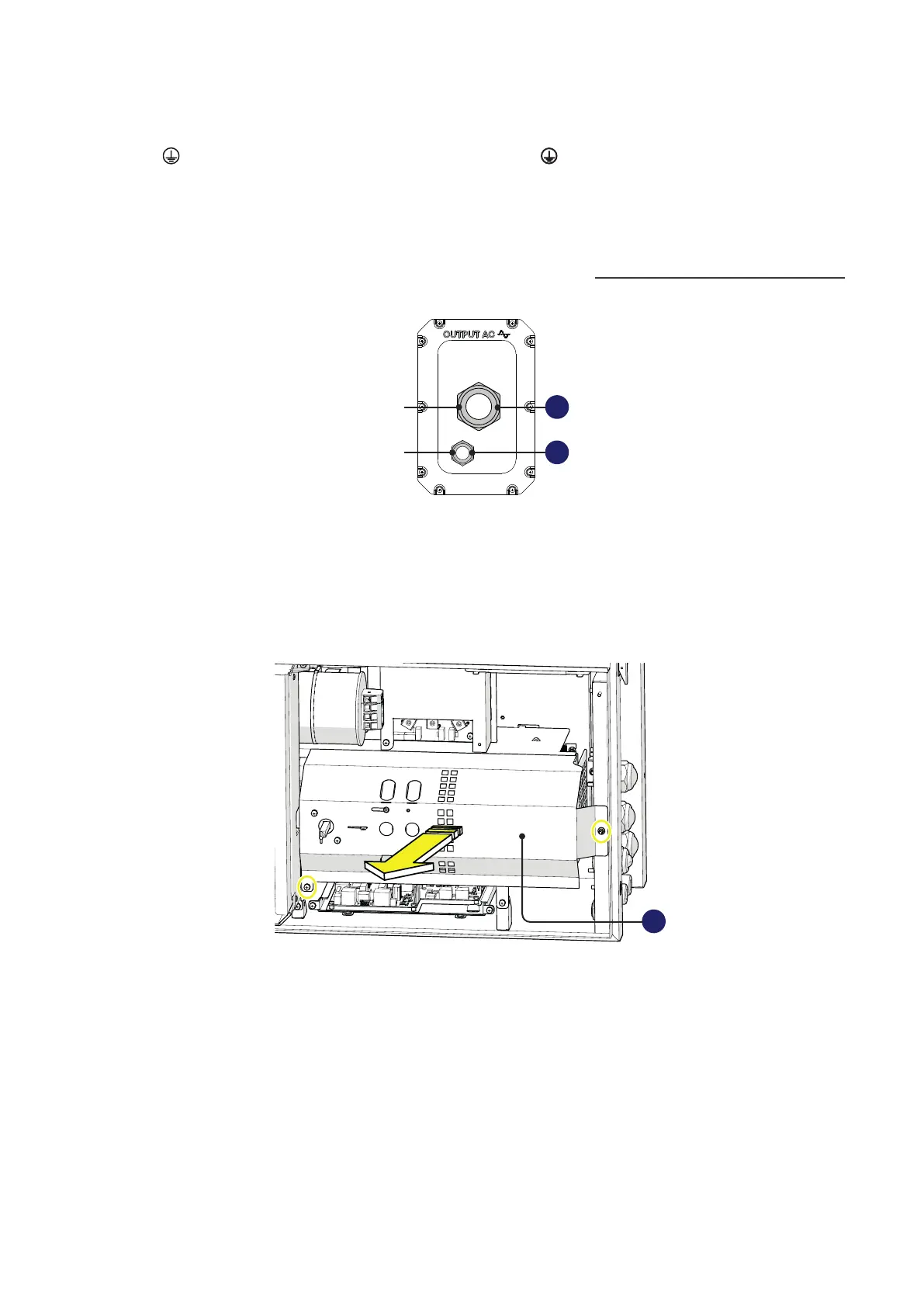
Multi-core configuration (optional):
one M63 cable gland (11) for the “R”, “S”, “T” phases and a M32 cable gland (12) for the grounding
cable
This version of the AC panel can be ordered separately. Refer to “Kit of recommended spare parts”
paragraph for further information.
11
12
PE
RST
PE
Follow the procedure below to route all the cables:
• Open the wiring box front cover (07).
• Remove the AC protective shield (23) by removing the M5 screw and the M5 nut.
23