Generator Faults
18.12.15 Kapitel/Chapter 8: Generator Faults - Seite/Page 191
(Note: The current arises from the rest magnetism of the rotor, which induces a voltage in the winding).
8.7.4 Measuring the Ohm Resistance of the Generator Windings
If a short circuit could not be found by using a multi-meter, then the windings parts of the generator must be
checked by means of an Ohmmeter that is suitable for low resistance values.
• Set the measuring device to measure resistance. If you hold the poles of the measuring device against each other,
then 0.00 Ohms should be shown. If the pole has been isolated then the display should show an overflow. Please
carry out this test to check the device.
• Measure the resistance within the individual windings.
If there are large deviations, it must be assumed that there is a windings short circuit. This also leads to non-
excitation of the generator.
The actual values between the windings parts and the earth cannot, however, be exactly determined. Fore-mostly,
the values of all three measurements must be the same, if possible. Deviations from each other show there is
windings short-circuit. In this case, the generator windings must be renewed by an electrician.
8.7.5 Check the Windings for Short circuit
Ensure that the generator has been switched off and cannot be inadvertently switched on. Disconnect the wires to
the battery for this.
1. All wires in the junction box or - if necessary - in the circuit distribution box must be disconnected. Ensure that the
wires are no longer carrying an electrical current, before being disconnected (see “Check and discharge the
capacitors” on Page 188.)
2. Remove the Bridges between „N“ and „PE“, so that the windings and casing do not come into electrical contact.
3. Make a check, by means of a Multimeter, as to whether there is a current between the individual winding
terminals and the casing (PE).
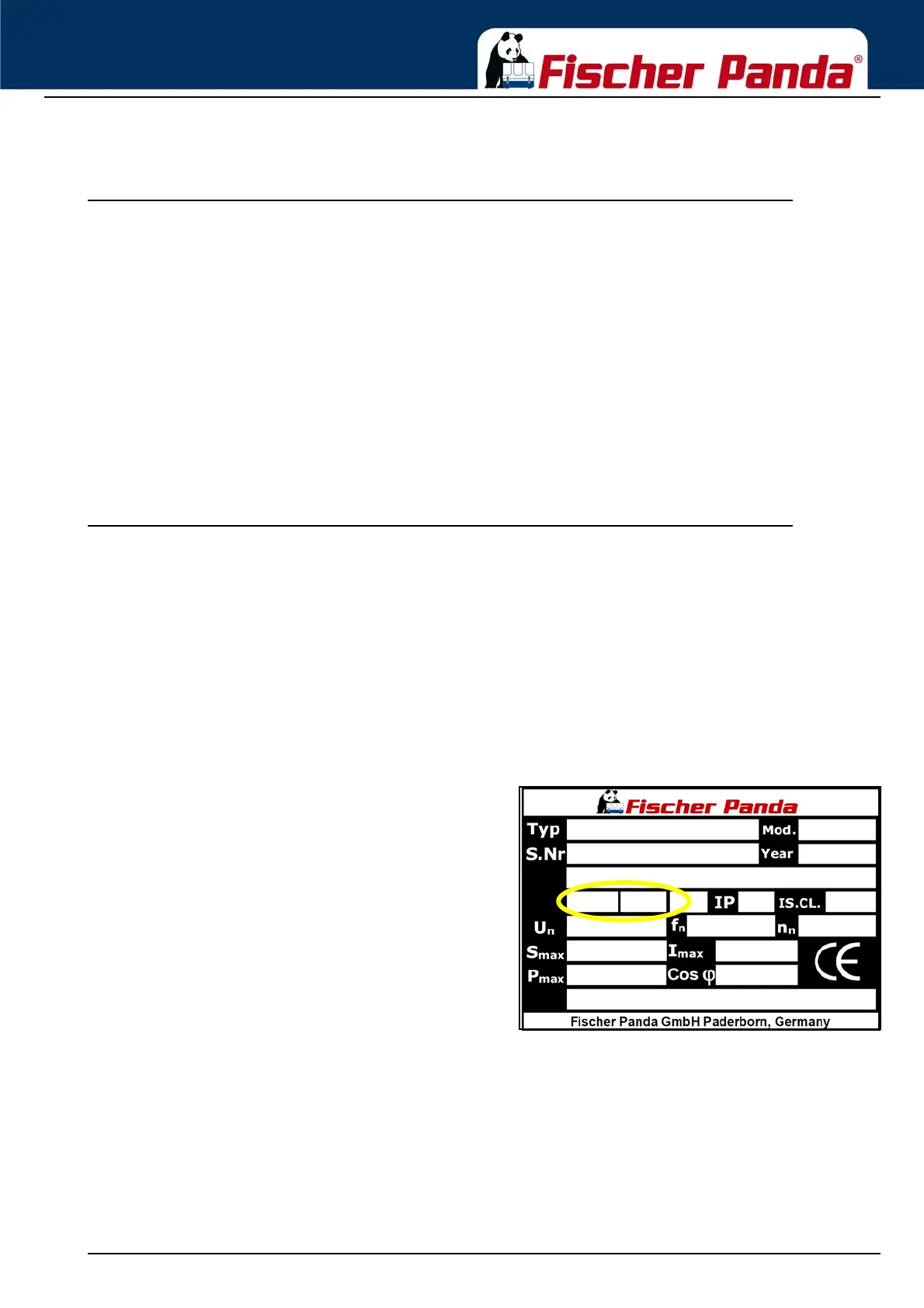
The contacts to measured are not relevant to the type of generator (see type plate):
Fig. 8.7.5-1: Generator type plateHP1 - 50 Hz: L, Z
HP1 - 60 Hz: L, Z
HP3 - 50 Hz: L1, L2, L3
HP3 - 60 Hz: L1, L2, L3, 1, 2, 3, 4
DVS - 50 Hz: L1, L2, L3, L1’
DVS - 60 Hz: L1, L2, L3, L1’, 1, 2, 3, 4
The generator must be sent for a check to the factory or be re-winded locally, when a pass (beep) should be
determined. Windings data can be requested for this, if it is necessary.