Installation Instructions
18.12.15 Kapitel/Chapter 6: Installation Instructions - Seite/Page 63
6.4.6 Generator installation below waterline
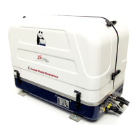
Fig. 6.4.6-1: Vent valveIf the generator cannot be attached at least 600 mm
above the waterline, a vent valve must be installed at the
raw water line.
Possible heeling must be taken into consideration if installed
at the "mid-ship line"! The water hose for the external vent
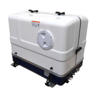
valve is located at the back of the sound insulated capsule.
This hose is split in the middle and extended respectively at
each end by an additional hose and a connecting nipple.
Both hose ends must be led outside of the sound cover, if
possible 600 mm over the waterline in the mid-ship line. The
valve is connected at the highest place to the two hose ends.
If the valve jams the cool water line cannot be de-aerated
after stopping the generator, the water column is not
discontinued and water can penetrate into the combustion
chamber of the engine. This will lead to damage the engine in
a short term!
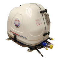
Fig. 6.4.6-2: Rubber hose for vent valve - example
The rubber hose for the external vent valve will be cut...
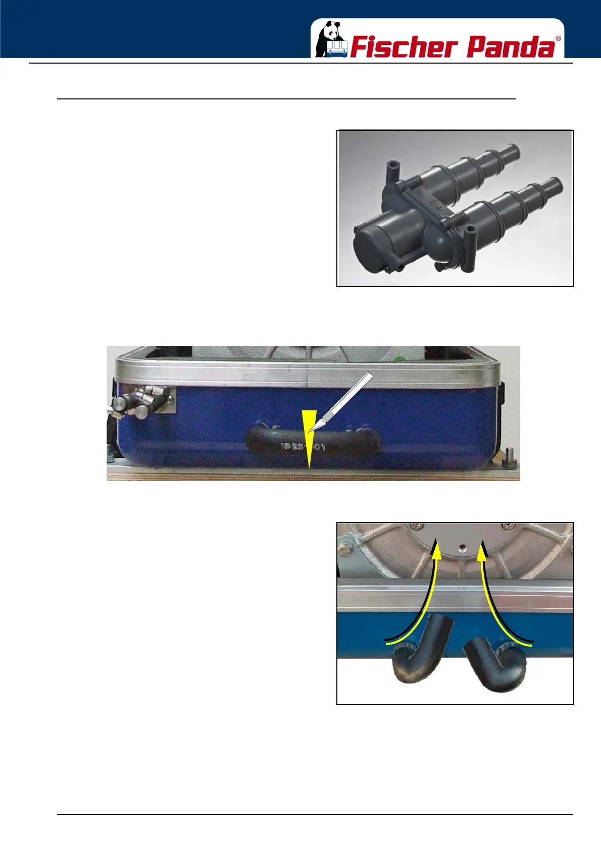
Fig. 6.4.6-3: Split rubber hose for vent valve ...and bend upwards.
Both hose ends will be extended respectively with a
hose and connected with a vent valve 600 mm over the
waterline.
Example