8 Connection
PIOX S72* 8.1 Transducers
71
UMPIOX_S72xV1-9EN, 2022-05-15
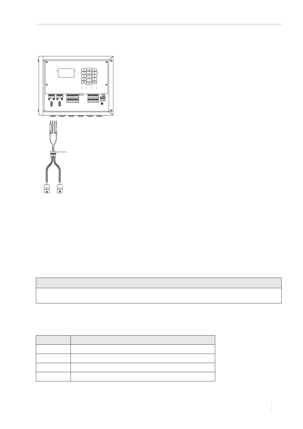
8.1.2 Connection of the extension cable to the transmitter
The extension cable is connected to the transmitter via the transducer connection.
• Remove the blind plug for the connection of the transducer cable.
• Open the cable gland of the extension cable. The compression part remains in the cap nut.
• Push the extension cable through the cap nut and the compression part.
• Prepare the extension cable.
• Shorten the external shield and brush it back over the compression part.
• Screw the sealing ring side of the basic part into the transmitter housing.
• Insert the extension cable into the housing.
• Fix the cable gland by screwing the cap nut onto the basic part.
• Connect the extension cable to the terminals of the transmitter.
Fig. 8.4: Connection of the transducer cable with stainless steel conduit and stripped ends to the
transmitter
1 – cable gland
For good electromagnetic compatibility (EMC), it is important to ensure good electrical contact between the external
shield and the cap nut (and thus the housing).
Tab. 8.4: Terminal assignment
terminal connection
AV white or marked cable (core)
AVS white or marked cable (internal shield)
ARS brown cable (internal shield)
AR brown cable (core)
A
B
SNAP
DISP
DISP
MODEFAST
MUX
NEXT
Q
ON
Q+Q-
3x Q
OFF
LAN
USB
A+
B-
P1+
P2+
P3+
P4+
P5a
P6a
P7a
S
S
P1-
P2-
P3-
P4-
P5b
P6b
P7b
X2 X3
X_AV
KL11
KL12
KL7KL8
KL9KL10
KL4
X_AR X_BV X_BR
T1A
T1B
S1
T2A
T2B
T3A
T3B
S3
T4B
T4A
T1a
T1b
S1
T2a
T2b
T3a
T3b
S3
T4b
T4a
N(-)
PE
L(+)
AV
AVS
AGN
ARS
AR
BV
BVS
BGN
BRS
BR