8 Connection
8.1 Transducers PIOX S72*
2022-05-15, UMPIOX_S72xV1-9EN
70
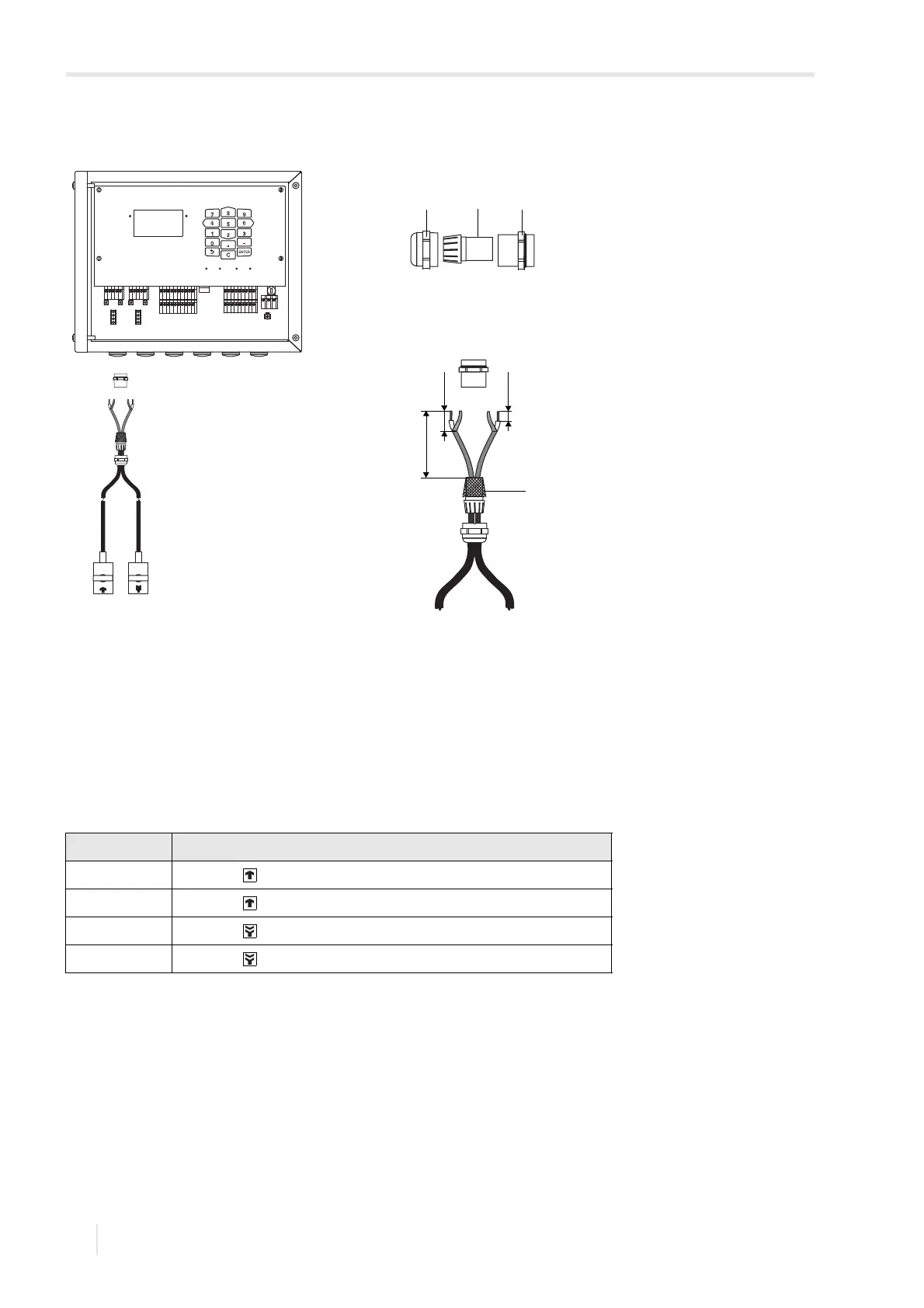
8.1.1.3 Transducer cable with stainless steel conduit and stripped ends
• Remove the blind plug for the connection of the transducer cable.
• Insert the transducer cable into the housing.
• Fix the transducer cable by tightening the cable gland.
• Connect the transducer cable to the terminals of the transmitter.
Fig. 8.3: Connection of the transducer cable with plastic jacket and stripped ends to the
transmitter
1 – cap nut
2 – compression part
3 – basic part
4 – external shield, brushed back
Tab. 8.3: Terminal assignment
terminal connection
AV transducer (brown cable, marked white)
AVS transducer (red cable)
ARS transducer (red cable)
AR transducer (brown cable)
A
B
SNAP
DISP
DISP
MODEFAST
MUX
NEXT
Q
ON
Q+Q-
3x Q
OFF
LAN
USB
A+
B-
P1+
P2+
P3+
P4+
P5a
P6a
P7a
S
S
P1-
P2-
P3-
P4-
P5b
P6b
P7b
X2 X3
X_AV
KL11
KL12
KL7KL8
KL9KL10
KL4
X_AR X_BV X_BR
T1A
T1B
S1
T2A
T2B
T3A
T3B
S3
T4B
T4A
T1a
T1b
S1
T2a
T2b
T3a
T3b
S3
T4b
T4a
N(-)
PE
L(+)
AV
AVS
AGN
ARS
AR
BV
BVS
BGN
BRS
BR