Multifunction Electrical Tester Calibrator
DUT Calibration Examples
165
Calibrate Continuity Testers
XW Warning
To avoid electric shock, use only high-quality, shrouded test
leads and adapters with the appropriate voltage rating between
the Product and instruments being calibrated.
Continuity is a low-ohms test function typically found on many electrical testers,
including insulation testers and installation testers. To perform a 2-wire
resistance calibration:
1. Push .
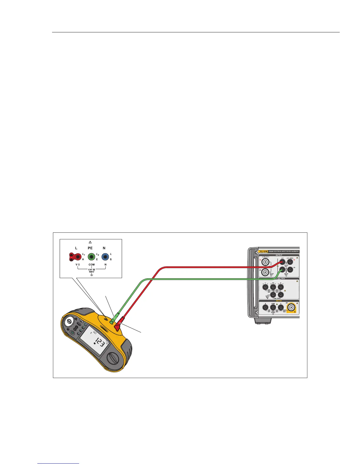
2. Using Figure 30 for a reference, connect the DUT to the Product’s LOΩ HI
and LO terminals.
3. Push the MODE softkey. Then, using the cursor keys or rotary knob, highlight
Resistance 2-Wire and select it by pushing the Select softkey or pushing in
the rotary knob.
4. In the OUTPUT area of the display, verify 2-Wire is displayed. If not, push the
MODE softkey and follow the instructions in step 3 above to select
Resistance 2-Wire.
5. Adjust the output value to the desired resistance.
6. Push .
The resistance is applied to the output terminals. Compare the reading on the
DUT with the standard value on the Product’s display.
Fluke 1653
L (L1/Red)
Fluke 5322A
PE
(L2/Green)
iep030.eps
Figure 30. 2-Wire Resistance Calibration DUT Connections
 Loading...