Multifunction Electrical Tester Calibrator
Calibrate Insulation Resistance Testers
175
Limitations of the Resistance Multiplier
For calibrations that use the resistance multiplier, limitations resulting from its
operating principle need to be considered. The resistance multiplier function is
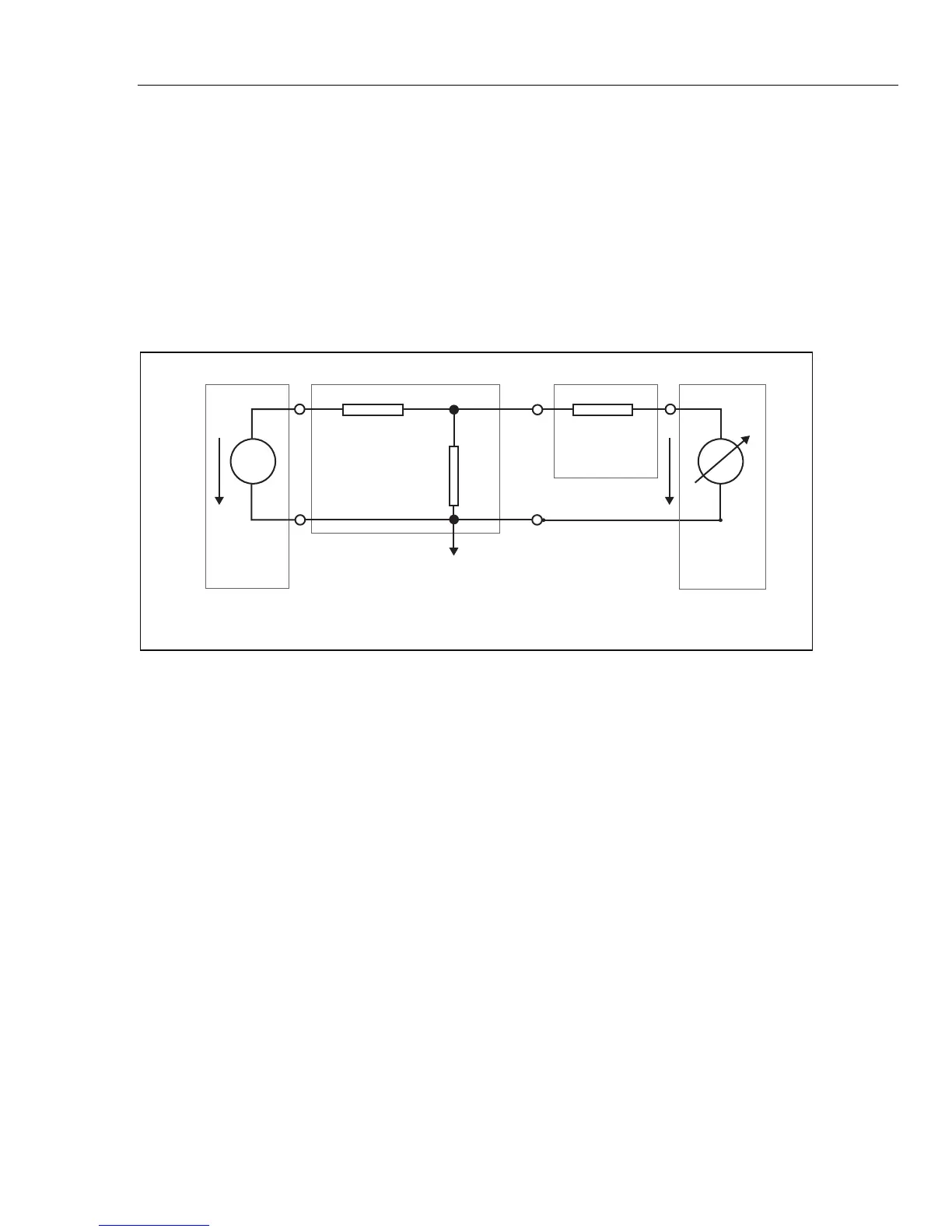
based on a passive T type resistance network. Referring to Figure 39, R21 is the
resistance effectively seen by the DUT.
R21 = V1 / I2 under the condition V2=0
The Product high resistance source is used as one of the parts of the resistance
network Rcal. The two resistors (R1 and R2) create a T network that are part of
the resistance multiplier option. Nominal multiplication coefficient of the multiplier
is 1000.
I2
R1
DUT
DUT
HV
Source
Resistance
Multiplier
5322A
Rcal
R2
R21 = R1 + Rcal + R1/R2 *Rcal
R1 = 300 Mohm
R2 = 300 kohm
V1
V2
iep181.eps
Figure 39. Resistance Multiplier
The multiplying principle has some limitations in actual usage. The resistance
multiplier is in fact a three-pole simulator of high resistance. It can be applied
successfully for insulation test meters which have a low sense terminal that sinks
test current created by its internal high voltage source when attached to the
resistance multiplier. To meet the conditions of the equation that defines R21, the
DUT low (sense) terminal has to work as a virtual ground.