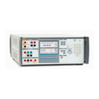
5322A
Operators Manual
40
Use the Ground Bond Resistance Mode
To set the Ground Bond resistance output:
1. Push .
The default mode is the resistance mode. The value used the last time the
ground bond resistance function was used is set and displayed in the
OUTPUT area of the display. If already in the Ground Bond Function, push
the softkey labeled MODE.
2. Using the cursor keys or rotary knob, highlight either Resistance 2W or
Resistance 4W and either push the Select softkey or push in the rotary
knob.
Note
When you use the 2W configuration, the Product relay-cleaning
procedure must be performed at periodic intervals. See Clean the
Ground Bond Resistance and Loop/Line Impedance Relays and the
5322A Specifications.
3. Set the resistance value using the rotary knob or keypad. If the entered value
is not exactly one of the 17 possible selections, the resistance closest to the
value entered will be selected.
4. Using the Terminals area of the display as a guide, connect the DUT’s
terminals to the Product PE and N terminals of the Z
L
, Z
GND
and RCD
terminals. These terminals are always floating from ground.
5. After confirming all settings and connections are correct, push to connect
the DUT to the selected resistance.
While connected to the DUT, the Product monitors the voltage and current
appearing across the resistance. The actual current flowing through the
resistance, the maximum value, along with the maximum allowed current, is
shown in the PARAMETERS area of the display.
All individual resistance outputs have two test current measurement ranges, high
and low. The ratio between them is 10:1 (see the 5322A Specifications at the
Fluke Calibration website). To switch from the high-current range (default) to the
low-current push the Lo curr softkey. The active selected current range is shown
on the display by the low current indication On and Off, with the line below
showing maximum applicable test current.
Ground bond resistor outputs are equipped with test lead resistance
compensation. When the test lead resistance is known it can be stored in
Calibrator memory. The display then shows calibration value of the selected
resistor plus the test lead resistance (Series resistance). To enter test lead
resistance push the Setup softkey, select Ground bond resistance and Series
resistance. Enter the resistance value using numerical keyboard, rotary buttons
or cursor keys. Currently stored test lead resistance is shown in the line Series
resistance. Test lead compensation is available in 2W mode only.