Multifunction Electrical Tester Calibrator
Calibrate Line Impedance Testers
183
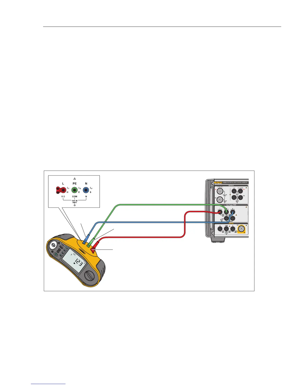
5. On the DUT, select the Line Impedance function, test signal, and test
condition. Refer to the DUT manual for information on setting these variables.
6. Adjust the Line Impedance to the desired output by using either the rotary
knob or or keys.
7. Push .
8. Push Start or Test on the DUT.
During the calibration, the PARAMETERS area of the Product’s display
indicates the measured test signal polarity, amplitude, and prospective fault
current (PFC).
9. When the DUT displays the measured line impedance, compare it to the
impedance displayed in the OUTPUT area of the Product’s display.
Note
When a new impedance is set on the Product, the resistance change
takes approximately 500 milliseconds.
10. Push to disconnect the output terminals from the DUT.
Use the Rescan function if necessary. Depending on the stability of the supplying
mains, perform a Rescan measurement once every 15 minutes when performing
Loop or Line Impedance calibrations for the best results.
Fluke 1653
Fluke 5322A
PE
(L2/Green)
L
(L1/Red)
N
(L3/Blue)
iep037.eps
Figure 44. Line and Loop Impedance Calibration on a Fluke 1653