Multifunction Electrical Tester Calibrator
Set the Low Resistance Source Output
33
2. If Open or Short or 10 mΩ single value is desired, push the Mode softkey.
Then, with the cursor keys or rotary knob, highlight Short 2-Wire, Short 4-
Wire, Open, or 10 mΩ push Select or push in the rotary knob to select. 10
mΩ value is available for 4-wire application only.
3. Set the resistance value with the keyboard, cursor keys or rotary knob.
The resistance for this function is output through the terminals with either a 2-
wire or 4-wire connection. For 2-wire resistance calibration, connections to the
DUT are made using the LOΩ HI and LOΩ LO terminals. For 4-wire resistance
calibration, additional connections are necessary using the LOΩ-SENSE HI and
LOΩ-SENSE LO terminals.
Note
4-wire resistance mode is used for low resistance calibrations of
DUTs equipped with the 4-wire measurement capability.
The resistance on the Product terminals can be either floating or grounded.
When grounded, the LOΩ LO terminal is connected to earth ground through the
ground in the power line socket using an internal relay. Whether the output is
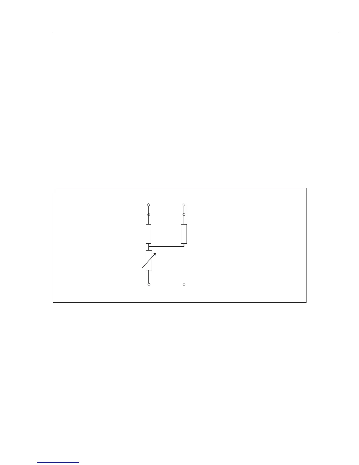
grounded is indicated in the Terminals area of the display. See Figure 3.
=
LO-OHM HI Terminal
LO-Ohm LO Terminal
LO-Ohm LO Sense Terminal
LO-OHM HI Sense Terminal
R
R
1 aux
R
2 aux
5322A Terminals
iep185.eps
Figure 3. Simplified Low Resistance Source Schematic
4. With the Terminals area of the display as a guide, connect the DUT terminals
to the Product OUTPUT HI and LO terminals.
5. After confirming the settings and connections are correct, push to
connect the DUT to the selected resistance.