5322A
Operators Manual
42
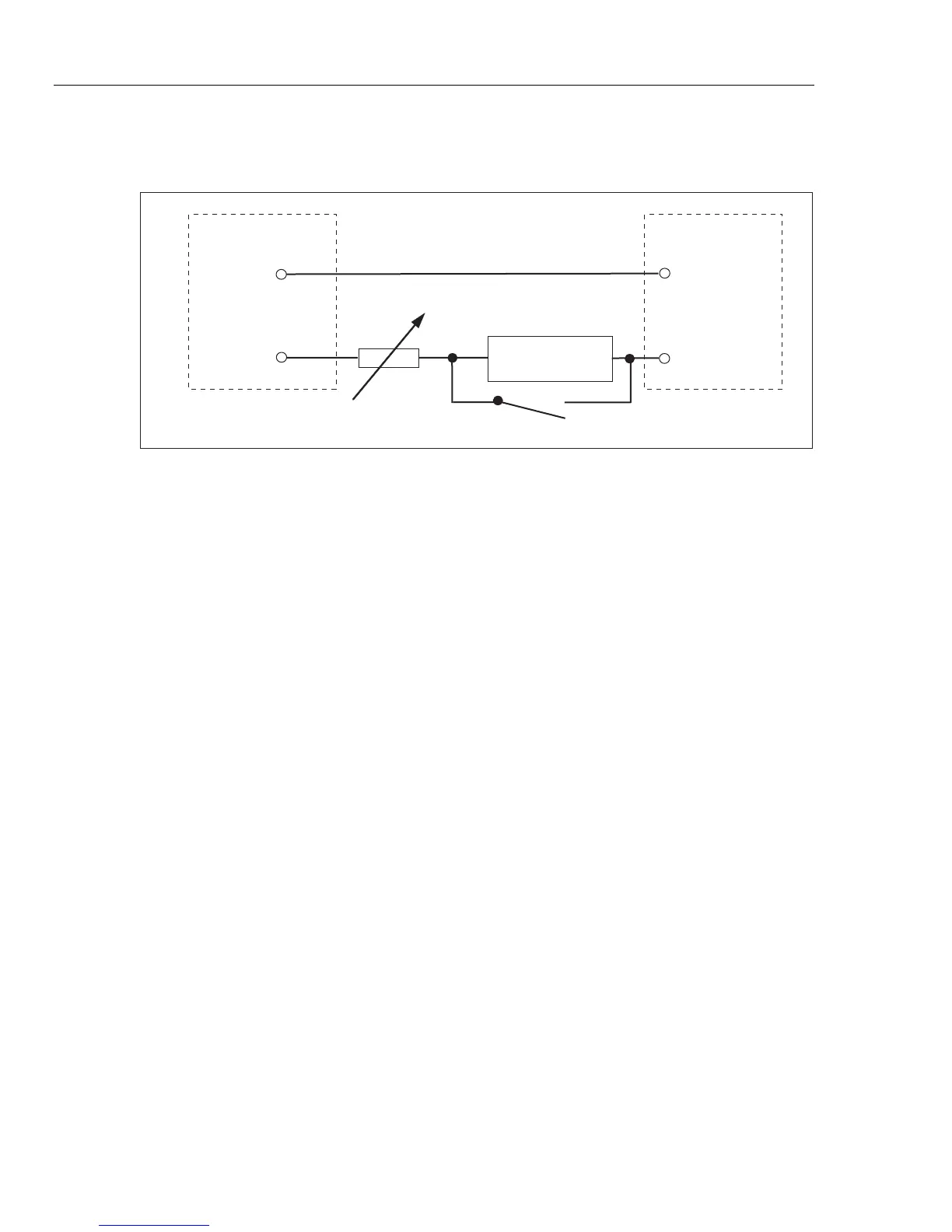
For line impedance calibration, an internal resistance is inserted between the N
terminal on the front panel and the Neutral of the power line input on the rear
panel. See Figure 6.
Neutral
Line
R
Front Panel
Z
L
, Z
GND
, RCD
N
Compensator
L
Fixed Mains
Socket/Outlet
iep013.eps
Figure 6. Simplified Line Impedance Source Schematic
For loop impedance calibration, the internal resistance is inserted between the
PE terminal on the front panel and N (Neutral) of the power line input on the rear
panel. During a loop impedance calibration, test current flows from the L wire in
the mains to the N terminal. Loop impedance calibration will not trip a protected
circuit unless the test current of the DUT is higher than the nominal trip current of
the installed residual current device (current breaker).
The resistance seen by the DUT is created using the selected resistance in
series with the actual residual impedance in the power line socket and power line
cable, and resistance of the test leads between the Product front panel terminals
and DUT.
The accuracy of the Loop/Line impedance function is influenced by the residual
line resistance. The Product offers these modes to deal with the actual residual
line resistance:
• OFF
• MAN
• SCAN
• COMP
If the power-up initial residual line resistance measurement is set to Off, and the
mode is set to SCAN or COMP, the Product first prompts you to perform the
resistance measurement. Use the Rescan softkey to start the procedure.