OmniSTAR 8200HP User Manual
Issue 1.07, 10/2008
50
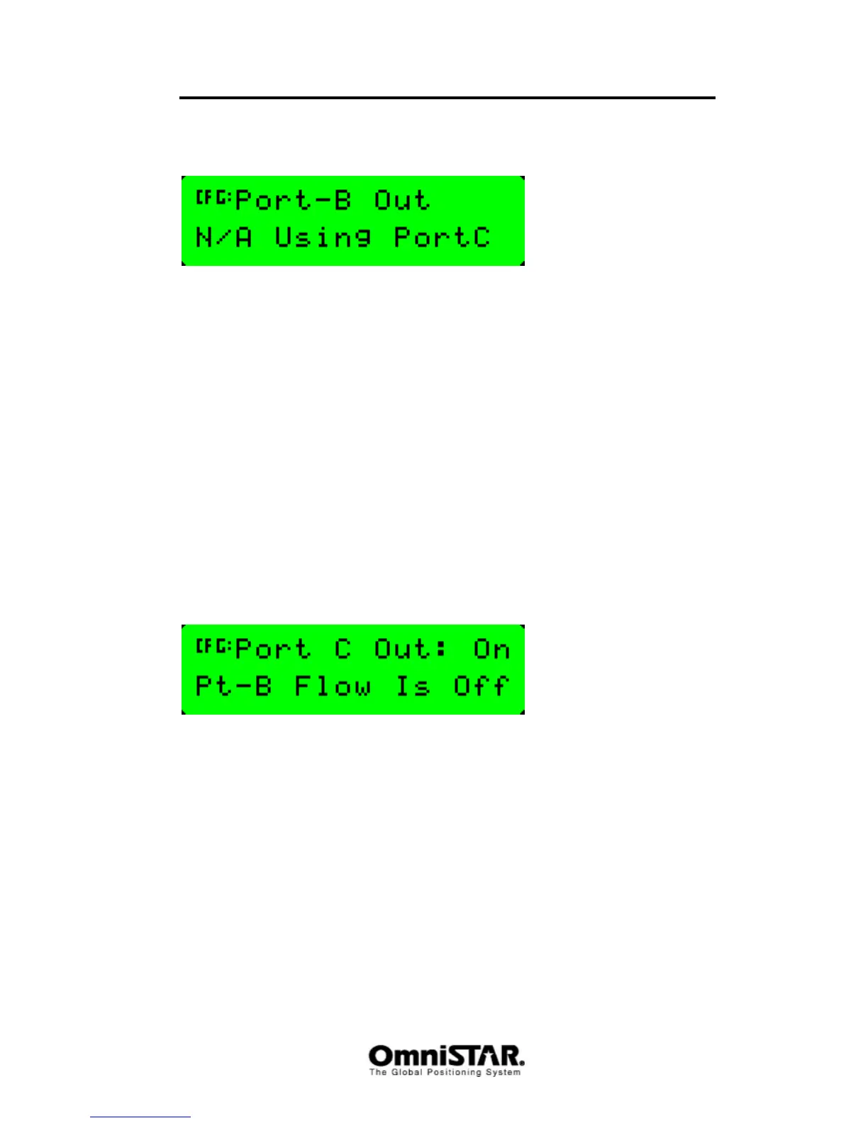
Port B In/Out
Figure 95: Port B I/O configuration settings
Although the 8200HP features three communication ports, there are only two
physical communication ports on the receiver back panel. In order to be able
to use all three communication ports, port B and port C are both connected to
physical power/data port B of the receiver. By default, Port C is set active to
use the physical power/data port, leaving Port B unavailable for
communication, as shown in Figure 95.
Sub-menu: Port C Config
The Port C configuration menu is similar to the Port A and Port B configuration
menu, although there are two differences. The first difference is only a
difference in menu order; the first and second menu items have changed
places, so the first menu item of the Port C configuration menu is the Port C
Out screen and the second menu item is the Port C In/Out configuration
setting screen. The second difference can be found in the Port C Out screen
itself as displayed in Figure 96.
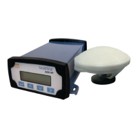
Port C Out
Figure 96: Port C Out screen
Port C cannot be configured to use RTS and CTS signals for modem control.
The port C out configuration screen is used to enable port C output (and with it
disable port B output) instead. When port C output is set active (‘On’), port B
output will automatically be disabled (‘Pt-B Flow Is Off’) and vice versa.
Sub-menu: CAN A Config
The 8200HP is capable of communicating using the CAN (Controller Area
Network) protocol. The CAN-bus is specifically designed to be robust in
electomagnetically noisy environments. Although it was initially designed for
the connection of electronic control units (ECUs) in the automotive industry, it
is ever more being used in embedded control applications where the risk of a
noisy communication path is high.