OmniSTAR 8200HP User Manual
Issue 1.07, 10/2008
57
R
eceiver Connector
Pin No.
S
ignal Name
S
ignal Description
D
B9 Connector
Pin No./lead
1 Event In External event input 4 (black)
2 TXD RS-232 transmit 2 (orange)
3 RXD RS-232 receive 3 (red)
4 NC
5 GND Signal ground 5 (shield)
6 RTS RS-232 RTS 8 (yellow)
7 PWR ON
1
Receiver power on
8 CTS RS-232 CTS 7 (green)
9 NC
10 V+ In Positive voltage lead
11 V- In Negative voltage lead
12 PPS 1 PPS output 9 (blue)
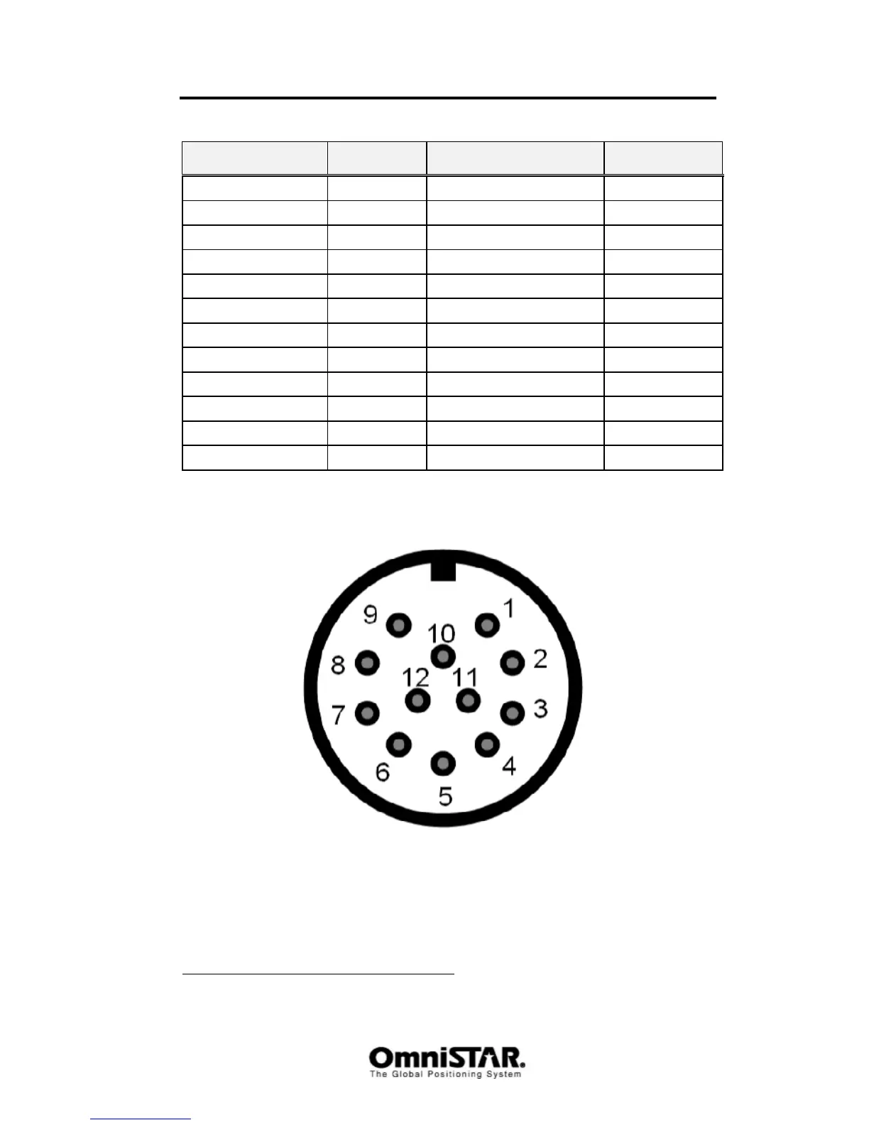
Table 9: 8200HP Power/data Port Pin-Out Descriptions (both port A and B)
Figure 106: Pin layout (receiver connector)
1
Pins 7 and 10 of Port A are jumpered with a 5 kOhm, 5% resistor.