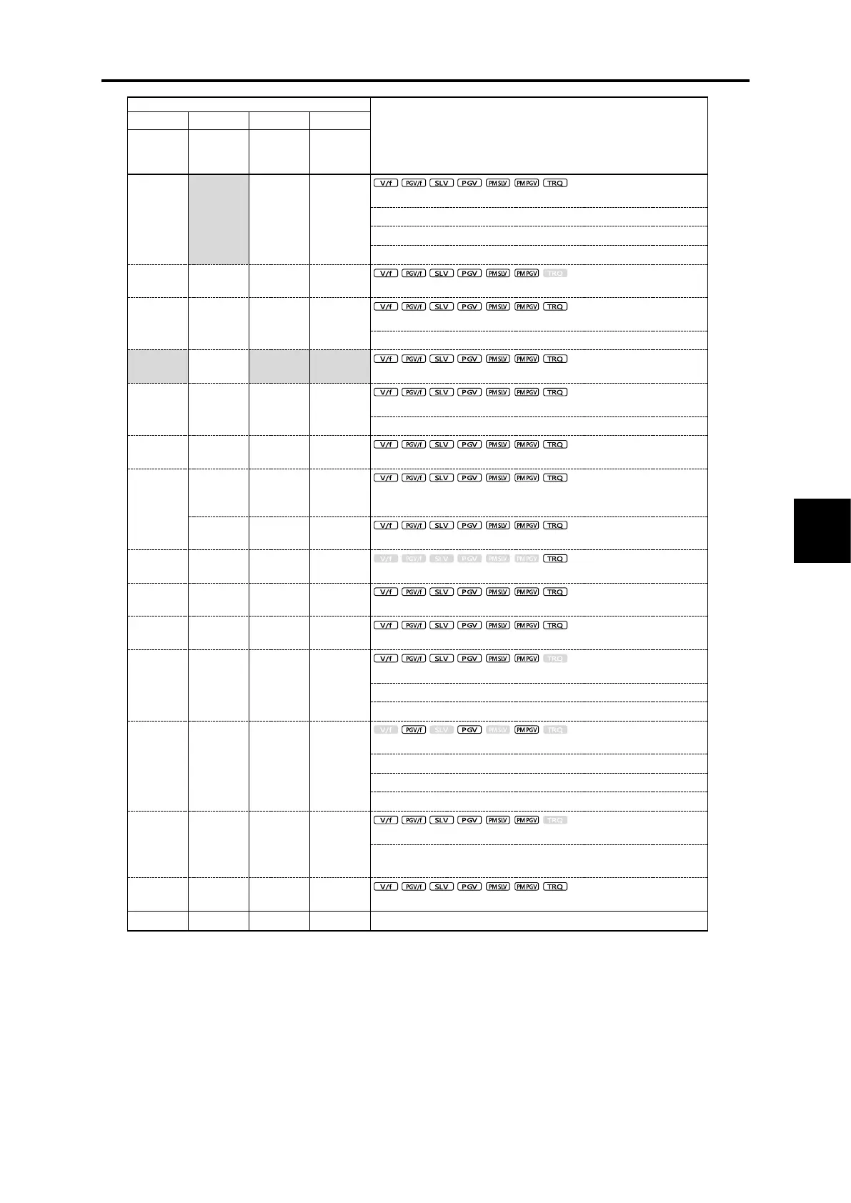
5.2 Function Code Tables
Control method and Data setting range
Terminal [Y1]
to [Y4],
[Y5A/C],
[30A/B/C]
Terminal
[Y1A/B/C] to
[Y4A/B/C]
90 (1090): Alarm content 1 “AL1”
91 (1091): Alarm content 2 “AL2”
92 (1092): Alarm content 4 “AL4”
93 (1093): Alarm content 8 “AL8”
95 (1095): Forced operation “FMRUN”
98 (1098): Warning “L-ALM”
99 (1099): Alarm output “ALM”
100 : No assignment “NONE”
101 (1101): EN circuit failure detected “DECF”
102 (1102): EN terminal input OFF “ENOFF”
105 (1105): Braking transistor broken “DBAL”
111 (1111) to 124(1124):
Customizable logic output signal 1 to 14 “CLO1” to “CLO14”
125 (1125): Integral power pulse output “POUT”
131 (1131): Speed limit level “S-LIM”
132 (1132): Torque limit level “T-LIM”
133 (1133): Low current detection “IDL2”
135 (1135): Dancer upper limit position warning signal “D-UPFL”
136 (1136): Dancer lower limit position warning signal “D-DNFL”
137 (1137): Dancer position limit warning signal “D-FL”
151 (1151): Overtravel detection “OT-OUT”
152 (1152): Forced stop detection “STOP-OUT”
153 (1153): Pass point detection 1 “
PPAS1
”
154 (1154): Pass point detection 2 “
PPAS2
”
158 (1158): Overload detected “LLIM”
159 (1159): Performing light load automatic double speed operation
“LAC”
251(1251): M/Shift key ON/OFF status “MTGL”
* Inside the ( ) is the negative logic signal (OFF at short-circuit).
*1: 6.00 s for FRN0115G2S-2G/FRN0060G2-4G or lower inverters, 20.00 s for FRN0146G2S-2G/FRN0075G2-4G or higher inverters

 Loading...


