Chapter 3. Wiring the AT600 Electronics
24 AquaTrans™ AT600 User’s Manual
3.1 Making the Electrical Connections (cont.)
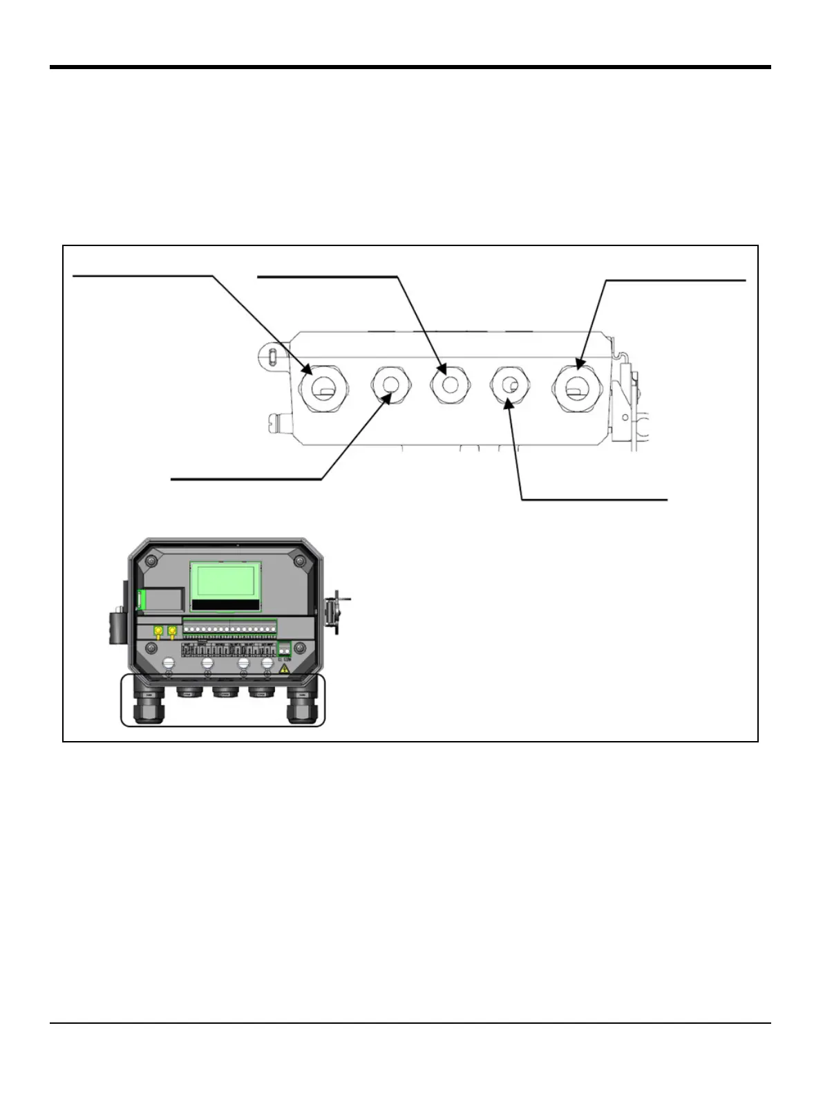
For proper wiring, the power lines, transducer cable and I/O lines must be routed through the appropriate
cable glands (see Figure 24 below). Also, refer to “Wiring Cable Specifications and Requirements” on page 177
for the required cable specifications.
IMPORTANT: Any unused cable glands must be plugged with the cable gland inserts provided with meter.
Figure 24: Recommended Cable Gland Usage
GLAND HOLE 5
GLAND HOLE 4
GLAND HOLE 2
GLAND HOLE 1
GLAND HOLE 3
DETAIL B
B
CABLE GLAND HOLES
Hole Num. Feed-Through Cables
1 Power Lines
2 Digital Output B Cable Lines
Digital Output C Cable Lines
Gate Input Cable Lines
3 Service Modbus Cable Lines
Customer Modbus Cable Lines
4 Analog Output A Cable Lines
5 Transducer Cable Lines

 Loading...


