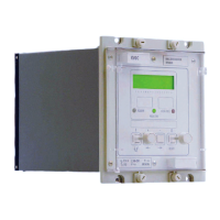
Manual
KVCG202/EN M/H
[Restore the following settings: dVs, and initial time delay (tINIT).]
9.6.3.4 Inter-tap delay
The relay should be commissioned with the settings calculated for the application.
If the voltage is not back within the deadband limits after the first tap change, then
additional tap changes will be initiated until the voltage level lies within the deadband
limits.
[Before making the following changes note the settings for: intertap delay (tINTER), and
deadband setting (dVs).
Set the intertap delay (tINTER) to 5 seconds and deadband setting (dVs) to 1%.]
Connect the timer to start from opening of the ‘Lower volts’ contact and stop on the
closing of the ‘Lower volts’ contact.
Apply 105% of Vs to the system voltage input (terminals 17 & 18).
Close switch S2 and wait for relay to give a tap change signal. Whilst a tap change pulse
is being given i.e. ‘CONTROL’ LED on the front of the relay is illuminated, reset the timer.
The timer will measure the inter tap time which runs from the instant the ‘CONTROL’ LED
extinguishes to the instant the ‘CONTROL’ LED illuminates again.
Check that the measured inter-tap time is within 4.975 seconds to 5.025 seconds
(i.e. tINTER ±0.5%).
Set the inter-tap setting to 0 seconds. Check the output is continuous, the ‘CONTROL’
LED should be continuously illuminated.
[Restore the following settings: intertap delay (tINTER), and deadband setting (dVs)].
9.6.4 Line drop compensation
9.6.4.1 Resistive load current compensation (Vr)
The relay should be commissioned with the settings calculated for the application.
Check the relay mode setting [0102 STATUS].
[Before making the following changes note the settings for: intertap delay (tINTER),
system voltage (Vs), circulating compensation voltage (Vc), resistive line drop
compensation setting (Vr), reactive line drop compensation setting (Vx), load current
setting (
IL)].
Set the:
- intertap delay (tINTER) to 0 seconds,
- system voltage (Vs) setting to 100V,
- circulating compensation voltage (Vc) setting to 0V,
- resistive line drop compensation setting (Vr) to required setting (or 10V),
- reactive line drop compensation setting (Vx) to 0V,
- load current setting (
IL) to 1In],
Apply a current of 1 x
In to the load current inputs (terminals 27 & 28). Apply the system
voltage and adjust the phase angle until the current leads the voltage by 90 degrees.
A tap change should be initiated (i.e. Raise or Lower volts). Alter the system voltage
(Vbc) until the relay stops tapping (i.e. both Raise and Lower volt contacts are open).
Determine the regulated system voltage Vreg read [0202 MEASURE]. Check the value of
Vr recorded as:
Vr = Vph – ph - Vreg ±0.5V or ±5% whichever is higher.
The measured line voltage Vph – ph can be read [0201 MEASURE]

 Loading...