Manual
KVCG202/EN M/H
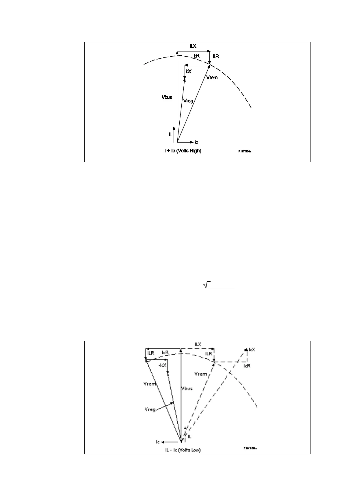
Figure 14: Effects of circulating currents on LDC IL+Ic (Volts High)
4.7.3 Negative reactance compounding
Since the effect of Ic on the Vxl setting is the main contributing factor to stability, a
reversal of the Vxl setting would produce components –IL.XL and –Ic.XL. The overall
effect is to obtain stable operation as the transformers are being driven towards the same
tap position.
Negative reactance control is an alternative form of compensation to pilot wire methods to
control circulating current between parallel transformers. It has the advantage over the
pilot method of control in that no interconnections are required between individual relays.
It is also applicable to parallel transformers of different impedance, tap changers or
source buses. Its main disadvantage is that it provides less accurate regulation than the
pilot method of control.
For reverse reactance control the V x l setting can be determined from the reactance of
the transformer.
V x l (reverse) = –
3 x Ip x XT
VT_ratio
where:
XT = reactance of the transformer
If the reactive compensation used in the above examples were reversed then the result
would be as shown by Figures 15 and 16.
Figure 15: Negative reactance control 1

 Loading...


