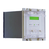
VCG202/EN M/H11
Technical
5.1.8 Load shedding/boosting
The effective regulated voltage can be lowered or raised by means of the load
shedding/boosting option. Three programmable levels are available which can be
selected either remotely via K-Bus or by energising one of the three opto inputs channels.
Each level can be set between 0 and ±10% and the selected values can be viewed under
the SYSTEM DATA heading of the menu system.
5.1.9 Undervoltage detector (V<)
Independent control is provided to detect undervoltage condition set between 80 and 130
volts. This function may be used to block operations that would lower the voltage further,
thus defining the minimum working limit of the transformer and allowing tap changes in
such a direction as to restore the regulated voltage. By using the output mask an output
contact may be set to operate for an undervoltage condition.
5.1.10 Overvoltage detector (V>)
Independent control is provided to detect overvoltage condition set between 105 and 160
volts. This function may be used to block operations that would raise the voltage further,
to prevent excessive voltage on busbars local to the transformers. By using the output
mask an output contact may be set to operate for an overvoltage condition.
5.1.11 Under/over voltage detector alarm delay timer (tV<V>)
Alarm initiation time delay can be set between 0 and 300 seconds. An alarm is initiated if
either the over or the under voltage detectors have operated.
5.1.12 Undervoltage blocking (V<<)
The undervoltage blocking settings can be set between 60 and 130 volts. Where the
system voltage falls below the set value, the undervoltage detector operates and
instantaneously resets the initial time delay thus inhibiting the relay outputs to ‘Raise’ or
‘Lower’ tap change operations. This feature provides an alternative method to overcome
the voltage fluctuations.
5.1.13 Circulating current detector (
Ic>)
The excessive circulating current detector settings can be set between 5% and 50%
of
In. In the event of excessive circulating current over a time period (tIC), set between 0
and 180 seconds, the detector can be used to internally block the relay for both raise and
lower operations and set an alarm.
Note: Separate external relay terminals are provided for 1A and 5A
inputs.
5.1.14 Overcurrent detector (
IL>)
The overcurrent detector setting can be set between 50% and 200% of
In. An alarm can
be initiated if the load current exceeds this setting.
Note:
In for the currents can be set via CONTROL column of the menu
system.
5.1.15 Undercurrent detector (
IL<)
The undercurrent detector setting can be set between 0% and 100% of
In. An alarm can
be initiated if the load current drops below this setting.
Note:
In for the currents can be set via CONTROL column of the menu
system.
5.1.16 Total number of tap change (TotalOps)
The total number of tap operations can be set between 1 and 10000. An alarm is initiated
if the number of operations exceeds the set value.

 Loading...