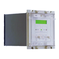
VCG202/EN M/H11
Technical
With negative reactance compounding use of a large negative reactance component will
give good performance in terms of keeping tapchangers in step but will increase the
susceptibility of the tapchangers to tap erroneously. This is due to increased errors in the
regulated voltage caused by changes in the power factor.
Figure 18 shows the errors that can be caused at a non unity power factor. Use of a
smaller negative reactance component will slightly increase losses due to circulating
currents but will greatly reduce susceptibility to erroneously tapchange due to changes in
power factor and will thus allow greater penetration of embedded generation.
To understand the difference in the required magnitude of negative reactance consider
the case where the tapchangers are just one step apart. The regulated voltage will be
increased in one VRR and decreased in the other by an amount proportional to the
negative reactance setting. If this amount exceeds half the deadband, then one or other
of the VRRs will immediately call for a tapchange and bring the tapchangers exactly into
line. If, on the other hand, the amount is less than half the deadband, it is possible that
neither VRR will call for a tapchange. However, as the load varies throughout the day the
next tapchange that does occur will bring the tapchangers exactly into line.
To achieve rapid and complete convergence the minimum negative reactance is
determined by the size of the deadband, which itself must exceed the step size of the
transformer. If, on the other hand the relaxed convergence is accepted the minimum
negative reactance is determined by the component tolerances. As explained earlier the
tendency for runaway is due to these component tolerances and so to prevent runaway
the action of the negative reactance must exceed this tendency.
The KVGC has a reverse current element which can be used to block tap changing or
change setting groups where there is reverse power flow caused by embedded
generation.
4.8 Supervision functions of a VRR
A range of supervision functions are required to provide a comprehensive voltage
regulating control scheme.
The supervision functions are employed to block unwanted tap changes and provide
alarms for various system conditions. These include the following:
4.8.1 Runaway protection
Runaway Protection is the feature that detects when a tap change has occurred and
checks that it is the result of an authentic tap change signal. An alarm is initiated if:
- tap position changes in the absence of an initiation signal, or
- tap position changes in a direction which causes the voltage to move further away
from the desired voltage Vs.
The run-away protection reads the flags set by the tap change initiation software to
determine when a fault condition occurs.
A locking/lockout condition is initiated to inhibit any further tap changes for a runaway
alarm if logic link [LOG7] is set to ‘1’.
If auxiliary power to the relay is interrupted then any difference in tap position between
power off and power on are counted by the operations counter but will not cause a run-
away condition. Any tap position changes occurring during an interruption to the system
voltage will be similarly treated.
4.8.2 Undervoltage detection (V<)
The undervoltage detector is set to a threshold V< which defines the minimum working
limit of the transformer. If the voltage falls below this limit, any tap change operations that
would reduce the voltage further are blocked. An independent time delayed output
contact allocated in the Relay Mask ‘V<’ indicates the operation of the element. A
common time delay t V< V> is used for the V< undervoltage and V> overvoltage
elements.

 Loading...