Manual
KVCG202/EN M/H
Where:
Ip = primary rated current of the line CT
RL = resistive component of line impedance
XL = reactive component of line impedance
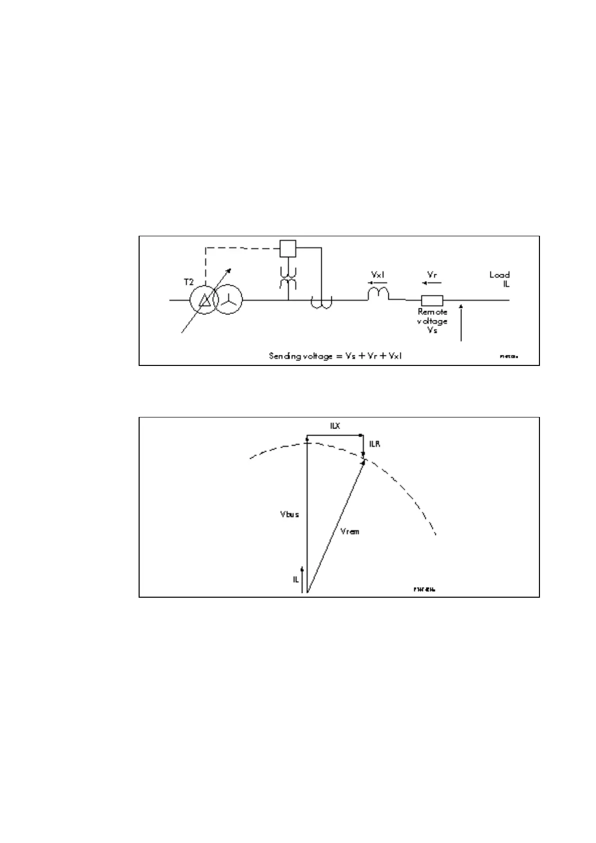
As can be seen from the above equations the KVGC is set in terms of the resistive and
reactive volt drop that will occur when rated current is applied to the relay. The relay then
applies a level of compensation proportional to the level of current. For example, a
setting of Vr = 20 V will produce a compensation voltage equal to 20 *Iload/Irated Volts.
Figure 9 below shows a vector diagram demonstrating the effect of the separate resistive
and reactive compensation applied to the relay.
Figure 8: Line drop compensation to regulate system voltage at remote point to
tap changer
Figure 9: LDC Vector diagram
4.6 Auto, manual and remote operation modes
The relay has the following modes of operation:
AUTO
MANUAL
BLOCK
REMOTE
It may be desirable before carrying out checks during commissioning to prevent tap
change initiation by selecting MANUAL operating mode.
The selection of AUTO/MANUAL modes can be made remotely or locally, by a menu
setting, a logic input which can be toggled or through the user interfaces.

 Loading...


