Manual
KVCG202/EN M/H
3. RELAY DESCRIPTION
3.1 Relay description
The KVGC202 voltage regulating relay use numerical techniques to derive control
functions. Six multiplexed analogue inputs are used, sampled eight times per power
frequency cycle. The Fourier derived power frequency component returns the rms value
of the measured quantity. To ensure optimum performance, frequency tracking is used.
The channel that is tracked is chosen, in order, from Vbc (low accuracy), external TPI
supply and
IL.
Eight output relays can be programmed to respond to any of the control functions and
eight logic inputs can be allocated to control functions. The logic inputs are filtered to
ensure that induced ac current in the external wiring to these inputs does not cause an
incorrect response. Software masks further enable the user to customise the product for
their own particular applications. They select/interconnect the various control elements
and replace the interconnections that were previously used between the cases of relays
that provided discrete control functions. An option is provided to allow testing of the
output relays via the menu structure.
The relay is powered from either a dc, or an ac, auxiliary which is transformed by a wide
ranging dc/dc converter within the relay. This provides the electronic circuits with
regulated and galvanically isolated supply rails. The power supply also provides a
regulated and isolated field voltage to energise the logic inputs.
An interface on the front of the relay allows the user to navigate through the menu to
access data, change settings and reset flags etc. As an alternative the relay can be
connected to a computer via the serial communication port and the menu accessed on-
line. This provides a more friendly and intuitive method of setting the relay, as it allows a
whole column of data to be displayed at one time instead of just a single menu cell.
Computer programs are also available that enable setting files to be generated off-line
and these files can then be down loaded to the relay via the serial communication port.
In addition to control functions the relay can display all the values that are measured and
many additional ones that are calculated. Useful time stamped data for post event
analysis is stored in event records. This data is available via a serial communication port
for access locally and/or remotely, with a computer. Remote control actions can also be
made and to this end K Range relays have been integrated into SCADA systems.
KVGC202 relay provide the user with the flexibility to customise the relay for their
particular applications. They provide many additional features that would be expensive to
produce on an individual basis and when the low installation costs are taken into account
it will be seen to provide an economic solution for tap change control.
3.2 User interface
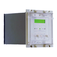
The front plate of the relay provides a man machine interface, providing the user with a
means of entering settings to the relay, displaying measured values and alarms.

 Loading...