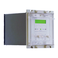
Manual
KVCG202/EN M/H
against those applied at the commissioning stage or any later changes that have been
made.
If a personal computer (PC) is used during commissioning then it is recommended that
the final settings applied to the relay are copied to a floppy disc with the serial number of
the relay used as the file name. The setting can then be readily loaded back into the relay
if necessary, or to a replacement relay.
9.8.3.4 “No service” alarm
This alarm flag can only be observed when the relay is in the calibration or configuration
mode when the tap control program will be stopped.
9.8.3.5 “No samples” alarm
This indicates that no samples are being taken. If this alarm flag is ever observed then it
might be possible to reset the flag by removing the auxiliary supply to the relay for 10
seconds. The relay should be returned to the factory if this problem is not resolved.
9.8.3.6 “No Fourier” alarm
This indicates that fourier not performing. If this alarm flag is ever observed then it might
be possible to reset the flag by removing the auxiliary supply to the relay for 10 seconds.
The relay should be returned to the factory if this problem is not resolved.
9.8.4 Records
9.8.4.1 Problems with event records
A total of fifty events can be stored in a buffer. The oldest event is overwritten by the next
event to be stored when the buffer becomes full.
The event records are erased if the auxiliary supply to the relay is lost for a period
exceeding the hold-up time of the internal power supply.
Any change of state of a control input or output relay, local setting change or alarm
conditions are stored in the relay.
Few events for change in state of logic inputs and relay outputs can be stored in the
event records. The change in state of inputs and outputs can occur frequently to generate
many events for each change in state occurrence. Setting System Data Link [SD7] to “0”
will turn off this feature and allow the maximum number of event records to be stored.
Events can only be read via the serial communication port and not on the LCD.
Any spare opto-inputs may be used to log changes of state of external contacts in the
event record buffer of the Relay. The opto-input does not have to be assigned to a
particular function in order to achieve this.
When a master station has successfully read a record it usually clears it automatically
and when all records have been read the event bit in the status byte is set to “0” to
indicate that there are no longer any records to be retrieved.
9.8.5 Communications
Address cannot be automatically allocated if the remote change of setting has been
inhibited by function link [0003 SD Links] link 1. This must be first set to “1”, alternatively
the address must be entered manually via the user interface on the relay.
Address cannot be allocated automatically unless the address is first manually set to 0.
This can also be achieved by a global command including the serial number of the relay.
Relay address set to 255, the global address for which no replies are permitted.
9.8.5.1 Measured values do not change
Values in the MEASURE column are snap-shots of the values at the time they were
requested. To obtain a value that varies with the measured quantity it should be added to
the poll list as described in R8514, the User Manual for the Protection Access Software &
Tool kit.

 Loading...