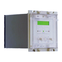
VCG202/EN M/H11
Technical
9.3 Auxiliary supply tests
9.3.1 Auxiliary supply
The relay can be operated from either an ac or a dc auxiliary supply but the incoming
voltage must be within the operating range specified in Table 1.
Relay rating (V) DC operating AC operating Maximum crest
range (V) range (VAC) voltage (V)
24/125 19 – 150 50 – 133 190
48/250 33 – 300 87 – 265 380
Table 1
CAUTION: The relay can withstand some ac ripple on a dc auxiliary supply.
However, in all cases the peak value of the auxiliary supply must
not exceed the maximum crest voltage. Do not energise the relay
using the battery charger with the battery disconnected.
9.3.1.1 Energisation from auxiliary voltage supply
For secondary injection testing using the test block type MMLG, insert test plug type
MMLB01 with CT shorting links fitted. t may be necessary to link across the front of the
test plug to restore the auxiliary supply to the relay.
Isolate the relay contacts and insert the module. With the auxiliary supply disconnected
from the relay use a continuity tester to monitor the state of the watchdog contacts as
listed in Table 2.
Connect the auxiliary supply to the relay. The relay should power up with the lcd showing
the default display and the centre green led being illuminated; this indicates the relay is
healthy. The relay has a non-volatile memory which remembers the state (ON or OFF) of
the led control indicator when the relay was last powered, and therefore the indicator may
be illuminated. With a continuity checker, monitor the state of watchdog contacts as
listed in Table 2.
Terminals With relay de-energised With relay energised
3 and 5 contact closed contact open
4 and 6 contact open contact closed
Table 2
9.3.1.2 Field voltage
The relay generates a field voltage that should be used to energise the opto-isolated
inputs. With the relay energised, measure the field voltage across terminals 7 and 8.
Terminal 7 should be positive with respect to terminal 8 and should be within the range
specified in Table 3 when no load is connected.
Nominal dc rating (V) Range (V)
48 45 – 60
Table 3
9.4 Settings
All relays will leave the factory with the recommended settings for the KVGC202 relay
under normal operating conditions, set for operation at a system frequency of 50Hz (refer
to Chapter 5 Section 5.3). If operation at 60Hz is required then this must be set as
follows:
From ‘SYSTEMS DATA’ menu, press the ‘F’ key until ‘0009 Freq 50Hz’ appears on the
lcd. Press the ‘+’ key until the display shows ‘0009 Freq 60Hz’. Then press the ‘F’ key
once more followed by the ‘+’ key to confirm the change.

 Loading...